


12
3.After completion of the above-men-
tioned two steps, the transmitter is kept in
a state of readiness. If the appliance
doesn’t working for a period time, just pull
out the plug from the 110V electrical
outlet.
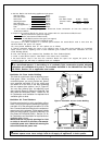
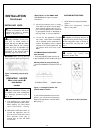
OPERATIONS OF
KEY-PRESS LOCKING
1.Key press locking:
when the burner is in operation or the
transmitter is in a state of readiness, just
press LOCK button on the operating
panel, there will be a “ ” symbol on the
LCD. If any button is pressed now, the
burner will not react at all.
2.Key-press unlocking:
when the burner is in a state of key-press
locking, first press
¨‹¨‹
¨‹¨‹
¨‹ , then press LOCK
button to unlock it (Child proof-See Fig16)
OPERATIONS OF
FAN
There are three selections: “AUTO” “MAN”
and “OFF”.When pushing the “FAN” button
on the “AUTO” select, the fan will be
controlled by the thermostat on the fan
blower unit. On the “MAN” select, the fan
will be kept in operation.To stop the
operation, push the “FAN”button to
“OFF”select.(See Fig16)
OPERATING HEATER
Continued
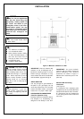
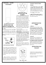
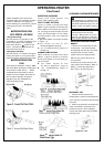
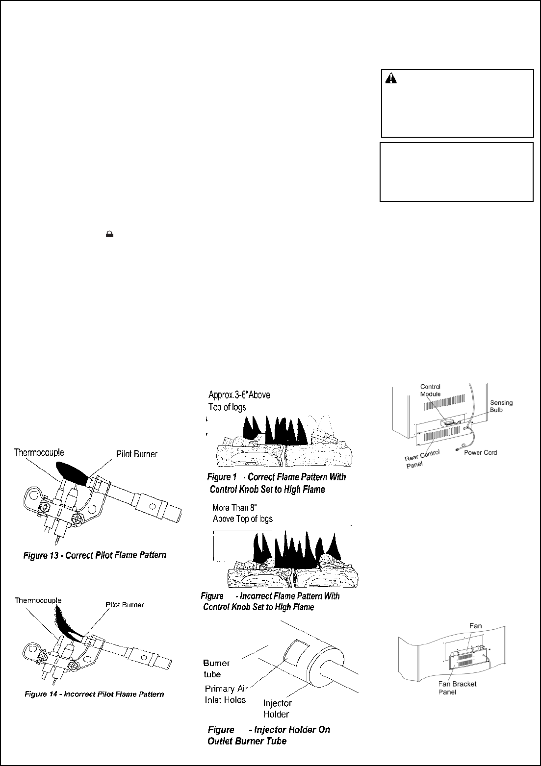
INSPECTING BURNERS
Check pilot flame pattern and
burner flame patterns often.
PILOT FLAME PATTERN
Figure 17 shows a correct pilot flame
pattern. Figure 18 shows an incorrect pilot
flame pattern. The incorrect pilot flame is
not touching the thermocouple.This will
cause the thermocouple to cool. When
the thermocouple cools, the heater will
shut down.
If pilot flame pattern is incorrect, as shown
in Figure 14:
turn heater off (see To Turn
Off Gas to Appliance, page 9)
see Troubleshooting (pages 12
through 13).
BURNER FLAME PATTERN
Figure 19 shows a correct burner flame
pattern. Figure 20 shows an incorrect
burner flame pattern. If burner flame pat-
tern is incorrect:
turn heater off (see To Turn
Off Gas to Appliance, page 9)
see Troubleshooting, pages 12
through 13
CLEANING AND MAINTENANCE
9
20
21
WARNING: Disconnect power be-
fore attempting any maintenance or
cleaning to reduce the risk of fire , elec-
tric shook or personal injury. Turn off
heater and let cool before cleaning.
CAUTION:
Label all wires prior to
disconnection
Wiring errors can cause
improper and dangerous operation.
when servicing
DISCONNECT WIRNG OR CONTROL
MODULE
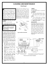
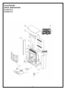
1. Remove four screws from the rear
control panel , take out thermostat
sensing bulb from the clip, then disco-
nnect the wires to free to control
module from its mounting location .
Note: Do not confuse the mark on
the each wire.
2. Remove two screws and hex nuts,
take out the control module. When in-
stalling , reverse the steps above.
(See Figure 22 and Figure 25 )
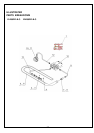
DISCONNECT FAN
1. Remove screws from the fan
bracket panel , pull the fan bracket panel
out to remove. Then disconnect two wires
free to fan.
2. Mark or tag each wire removed for its
exact reconnection. Remove the four
screws from the fan .when installing ,
reverse the steps above.(See Figure23
and Figure 25)
Figure 22- Control Model
Figure 23- Fan
controls
.
Verify proper operation after servicing.