


7
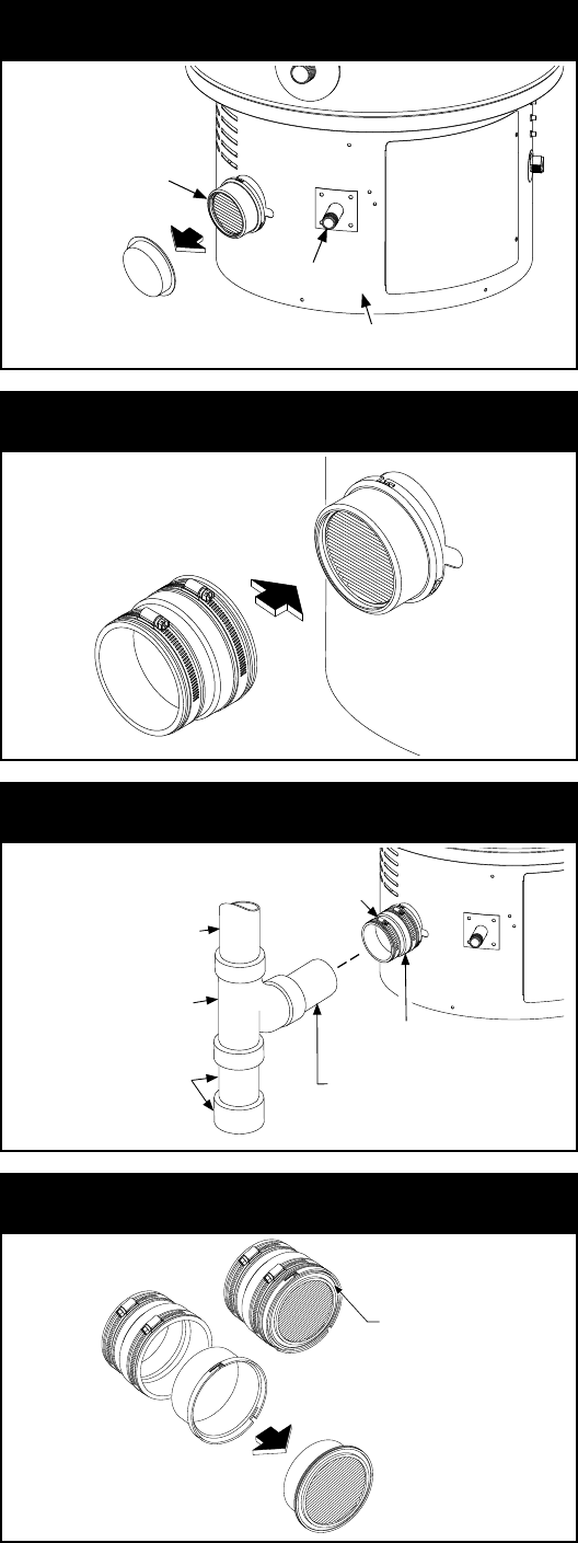
Integrated Filter Installation
When installing the adaptor rubber boot, note the following:
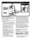
• Remove and discard the plastic cap from the outer
clamshell housing (see figure 4A).
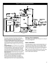
• To connect the heater to the air inlet, use the vent
adaptor rubber boot provided in the base skirt. The
adaptor rubber boot is designed for 3” venting (see
figure 4B). Note: If there is a need for 2” venting, then
use plastic pipe and fittings to transition down.
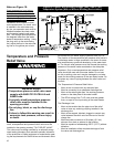
• Loosen the hose clamp at the adaptor rubber boot and
slide the plastic piping into the adaptor rubber boot.
With piping in place, tighten the hose clamp. Install a
3” x 3” x 3” TY drain/waste/vent fitting to trap airborne
particulates (see figure 4C). Note: If piping has been
previously cut with a saw, be sure to remove all burrs
and plastic shavings from the piping before installing.
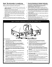
Preventive Maintenance
The heater is designed to shut down if the pressure
switch senses that the air inlet vent or the exhaust vent
is restricted. In this case, the pressure switch will open
and the heater will generate a 2-flash code (see the
troubleshooting section). If troubleshooting section of
this manual indicates that there is a blockage, note the
following:
• Turn off the gas supply to the water heater at the
manual gas shut-off valve, and disconnect power to the
water heater.
• To inspect the filter, loosen the hose clamp at the adap-
tor rubber boot and slide the plastic pipe out and away
from the adaptor rubber boot (see figure 4C).
• Remove the adaptor rubber boot containing the outer
clamshell housing by turning clockwise approximately
1/2” (30.5 cm) and pulling off of the internal clamshell
housing (see figure 4C).
• Using your fingers or a small flat blade screwdriver,
remove the filter media from the outer clamshell hous-
ing, handle carefully (see figure 4D).
• To clean filter, lightly tap the back of the filter support
to dislodge any large debris. Smaller debris may be re-
moved by using a vacuum cleaner. the filter media may
be cleaned by dipping the filter media into a solution of
warm soapy water and rinsing in clean water. Do not
scrub, allow to air dry before reinstalling. Filter media
may be cleaned on an average 2 to 3 times before
replacing with a new filter media is required.
• Reinstall the filter media by doing the above steps in
reverse order.
• Turn on the gas supply and reconnect power, refer to
the operating instructions on front of the water heater.
Verify proper operation of the water heater before
leaving.
Note: The heater must never be operated without the
filter media installed.
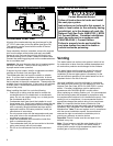
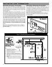
Figure 4B: Adaptor Rubber Boot
Push On &
Tighten Clamp
Adaptor Rubber
Boot
Outer Clamshell
Housing
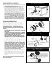
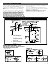
Figure 4C: Air Inlet Piping
Hose Clamp
3” Plastic Pipe
Adaptor Rubber Boot
Outer Clamshell Housing
3” x 3” x 3” TY DWV Fitting
(Position Cure Slope Upward)
Piped To
External Air
Supply
Install A Small Portion
Of Pipe And A Pipe Cap
To Rest On Floor.
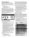
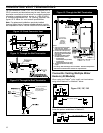
Figure 4D: Filter Media
Adaptor
Rubber Boot
Remove
Filter Media
Filter Media shown inside
the Outer Clamshell Housing
Outer Clamshell
Housing
NOTE: if found difficult to
reattach the outer clamshell
housing to the internal clamshell
housing - apply a thin layer of silicone
grease to the surface of the black rubber
support of the Filter Media.
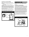
Figure 4A: Remove Plastic Cap
Outer Clamshell
Housing With Filter
Base Skirt
Gas Piping
Remove
Plastic Cap