


3. For all models, unscrew the screw or the lock until the front
of the cover is free from the top panel.
4. With the unit on a workbench or table, hold the cover
stationary. Remove the top panel by grasping it and pulling
it rearward, then upward for about 51 mm (2 in ), and
finally rearward again until the slots in the top panel have
cleared the studs in the cover.
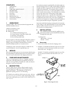
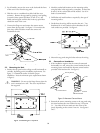
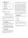
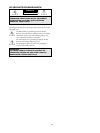
5. Unscrew the flange nut and remove the camera mount
system from the top panel. See figure 2. Do not lose the
parts, they will be needed to mount the camera and
reassemble the unit.
Figure 2: Removing the Mount System
5.2 Mounting the Unit
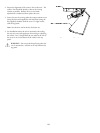
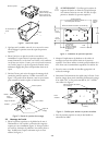
1. Position the top panel on the ceiling or wall, horizontally or
vertically, depending on the installation requirements. See
figure 3. A smooth flat surface is ideal for proper
installation. Note the minimum space requirements shown
in figure 3.
WARNING! - Do not use the hinge feature when the
unit is mounted on a wall. The cover may fall from
the top panel.
Figure 3: Positioning the Top Panel
2. Mark the anchor bolt locations on the mounting surface
using the holes in the top panel as a template. At least four
8-mm (5/16-in.) anchor bolts will be needed. Use of six
bolts is recommended.
3. Drill holes and install anchors as required by the type of
mounting surface.
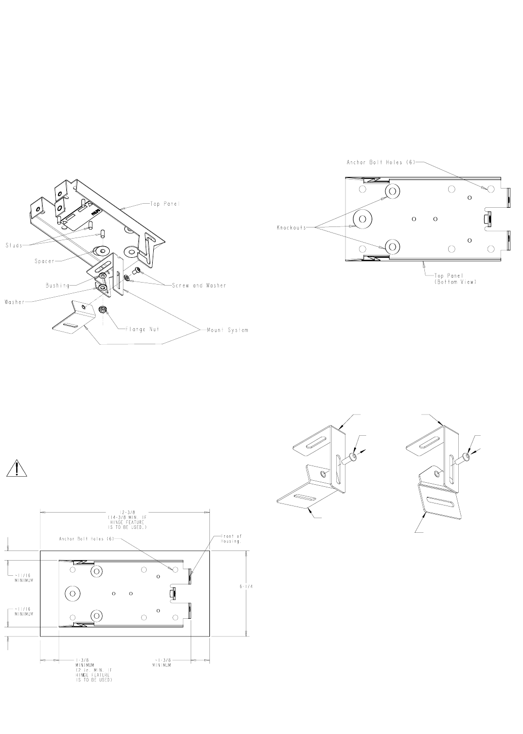
4. Decide how the wiring will be routed to the unit. Two
knockouts for ½ inch conduit and one knockout for 3/4
inch conduit are provided. See figure 4.
Figure 4: Bolt Holes and Knockouts
5. Mount the top panel using the bolts and rout the wiring.
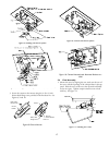
5.3 Camera/Lens Installation
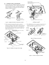
1. If the installation requires that the camera be mounted
horizontally to a wall, remove the camera bracket from the
mounting system and install the alternate camera bracket
provided in the hardware kit. See figure 5.
Figure 5: Alternate Camera Mount
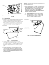
2. Reattach the camera mounting system to the top panel using
the same hardware that was removed in step 5 of section
5.1. Use either of the two studs near the center of the
panel, depending on the camera / lens size. See figures 6
and 7.
1.6
Mounting Bracket
Screw
Screw
Camera Bracket
Alternate
Camera Bracket
W9404408AE