


11
ThermalFlo Installation and User’s Guide
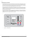
Electrical Connections
WARNING —Risk of electrical shock or electrocution.
This heat pump contains wiring that carries high voltage. Contact with these wires could result in death
or serious injury to pool or spa users, installers, or others due to electrical shock, and may also cause
damage to property. Always disconnect power circuit before connecting the heat pump.
CAUTION — Label all wires prior to disconnection when servicing controls. Wiring errors can cause improper and
dangerous operation. Verify proper operation after servicing.
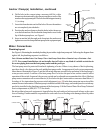
General Information
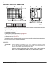
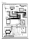
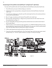
Wiring connections must be made exactly as shown in the wiring diagram found on the inside of the heat pump
access panel, see Figure 11 on page 12. The heat pump must include a definite means of grounding and
bonding. There is a ground lug inside the heat pump electrical compartment and a bonding lug on the left side
of the heat pump.
Main Power
Electrical wiring to the heat pump must be in accordance with the latest edition of the National Electric Code
(NEC), ANSI/National Fire Protection Association (NFPA) 70 in the United States, and in Canada, the
Canadian Electrical Code (CEC) C22.1, unless local code requirements indicate otherwise. All wiring must be
done by a certified electrician.
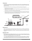
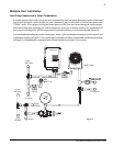
The following is the procedure to wire the ThermalFlo HP to the electrical source:
Be sure the power to the circuit for the heat pump is turned off.
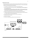
1. Remove the front left panel of the heat pump cabinet, (you do not need to remove the torque head
screw at the top left corner).
2. Remove the service panel to the heat pump electrical compartment. (front left corner of unit)
3. Electrical supply lines must be run through watertight conduit. Run the wires and conduit from the power
source and connect them to the conduit connection on the left side of the heat pump.
4. Connect the power leads to the terminals on the main contactor as shown in the wiring diagram.
5. Verify that all other contactor wires are secure, they may have loosened during shipment.
6. Connect the ground wire to the ground lug provided on the bottom of the electrical compartment.
7. Replace the service panel and reinstall screws to hold it in place.
8. Replace the front left panel.
9. Connect a copper bonding wire (8 AWG) to the bonding lug on the left side of the heat pump.
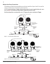
Bonding
CAUTION — This heater must be connected to a bonding grid with a solid copper wire not smaller in diameter
than 8 ga.
The National Electrical Code and most other codes require that all metallic components of a pool structure,
including reinforcing steel, metal fittings, and above ground equipment be bonded together with a solid copper
conductor not smaller than 8 AWG. The heat pump, along with pumps and other pool equipment must be
connected to this bonding grid. A bonding lug is provided on the left side of the heat pump to ensure this
requirement is met.