


Page 4
CAUTION
To avoid costly equipment damage, after verifying
proper water flow and prior to putting system into
normal operating conditions, flush the system using
Backwash mode until the waste water is clean.
Refer to Section 4 for Backwash mode operation
instructions.
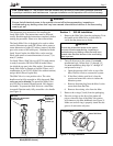
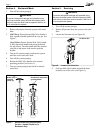
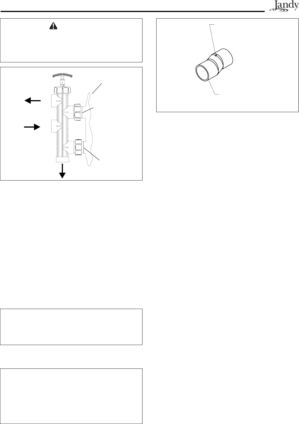
Figure 4. Jandy Versa-Coupler
Alignment
Mark
Versa-
Coupler
p/n 8044
CAUTION
Do not let any adhesive get inside the Slide Valve
body. Adhesive inside the valve body will prevent the
piston from moving freely, or cause the valve to leak.
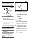
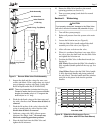
To Pool
(PORT A)
To Waste (PORT E)
From
Pump
(PORT B)
Figure 3. SVLV8 Installed on Jandy DEL48 or
(DEL60)
5. Hold the Slide Valve upright and place onto the
fi lter bulkheads (see Figure 3).
6. Tighten both union nuts to secure the valve on the
fi lter.
7. Place fi lter and valve in proper location on the
equipment set pad.
8. Plumb the discharge of the pump into the Slide
Valve inlet labeled
PORT B
.
9. Plumb the Slide Valve outlet labeled
PORT A
to the
heater or pool return lines.
10. Plumb the Slide Valve outlet labeled
PORT E
to the
waste line as needed. Allow the connections to dry
for 24 hours.
NOTE: For new installations other than Jandy DEL48
or DEL60, use the SVLV2 and the Versa
Coupler Kit, p/n 8044 (See Figure 4).
If using the Slide Valve with a Pentair fi lter, use
Pentair Pool Products™ Union Set #27002, and
then proceed to section B. If using a Sta-rite
fi lter, use Sta-Rite
®
Union Set #PKGM188, then
proceed to section B.
Section 2. SVLV2 and Versa-Coupler
Installation
NOTE Certain fi lters may require only one (1) versa-
coupler (p/n 8044).
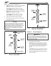
1. Slide one versa-coupler into
PORT C
and one into
PORT D
on the Slide Valve.
2. Hold the Slide Valve up to the fi lter and twist the
versa-couplers until they slide into the fi lter inlet
and outlet ports.
NOTE Make sure to align each versa-coupler to the
fi lter and the Slide Valve prior to gluing the
assembly. When the parts are in alignment,
mark each piece to ensure correct reassembly.
3. Remove the valve from the fi lter. Clean the versa-
couplers and glue them onto the valve using the
alignment marks as a reference.
4. Clean the versa-coupler and glue onto the fi lter.
Hold the coupler in place for a minimum of one
(1) minute.
5. Plumb the discharge of the pump into the Slide
Valve inlet labeled
PORT B
.
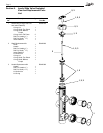
CAUTION
The Slide Valve has molded labels on each port (see
Figure 1). The ports on the SVLV8 are equipped with
union connections that match the connections on the
filter ports. Do not use pipe sealants on union nuts.
11. When the glue is dry, start the system and check
for proper water fl ow.
To Filter Body
(cut away view)
Filter Outlet
(PORT C)
Filter Inlet
(PORT D)