


Pelco Manual C324M-I (8/98) 7
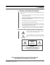
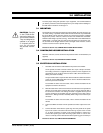
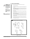
CAUTION:
Pan/tilts
in the PT280-24 Se-
ries are for indoor use.
Do not install outdoors.
They are designed to
operate in an upright
or inverted position
only. Do not mount
the pan/tilts horizon-
tally.
3.0 INSTALLATION
To ensure proper wiring and operation of your equipment, it is recommended that
you test the pan/tilt and associated equipment in your facility before installing it in
the field. Refer to Sections 3.2 through 3.4.
3.1 MOUNTING
The pan/tilt unit can be mounted upright or inverted. Attach it to a flat surface. If you
use a wall, ceiling, or pedestal mount, follow the instructions that are provided with
the mount. Make sure the mounting surface can support four times the combined
weight of the pan/tilt, enclosure, camera and lens. The PT280-24P and PT280-
24P/PP models weigh 9 pounds (4.05 kg). The PT280-24SL and PT280-24SL/PP
models weigh 11 pounds (4.95 kg). Refer to the manuals for your enclosure, cam-
era, and lens for the weights of those units. The weight of the enclosure, camera
and lens must not exceed 15 pounds (6.81 kg).
Proceed to Section 3.2, CAMERA/ENCLOSURE INSTALLATION.
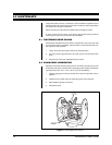
3.2 CAMERA/ENCLOSURE INSTALLATION
Attach the enclosure, camera and lens to the pan/tilt unit with 1/4-20 hardware (not
supplied).
Proceed to Section 3.3, ELECTRICAL INSTALLATION.
3.3 ELECTRICAL INSTALLATION
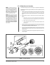
1. Assemble and connect the cable between the pan/tilt and controller.
On the pan/tilt, the cable connects to either the 14-pin or 28-pin connector.
The mating connector is supplied with the pan/tilt as loose equipment. To
assemble the 14-pin or 28-pin connector to the cable, refer to Section 3.3.1,
Mating Connector Assembly.
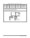
The pan and tilt motors require 24 VAC. Refer to Table A to determine the size
of wire to use. An RB24 Relay Box can be used to extend the distance be-
tween the pan/tilt and controller.
To assemble the other end of the cable, refer to the documentation for the
equipment to which it will connect.
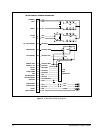
2. Make the cable for the camera lens functions and connect it to the pan/tilt and
camera. On the side of the pan/tilt is either a 6-pin or 9-pin connector that is
for camera lens functions. The mating connector is supplied with the pan/tilt
as loose equipment. To assemble the 9-pin connector to the cable, refer to
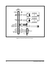
Section 3.3.1, Mating Connector Assembly. Refer to Figure 2 to wire the 6-pin
connector.
To assemble the other end of the cable, refer to the documentation for the
camera.
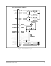
3. Connect the BNC connector from the pan/tilt to the video output of the cam-
era.
4. Connect the black wires with the spade lugs from the pan/tilt to the power
input on the camera. The other ends of the wires go to pins 9 and 14 of the
14- or 28-pin connector as shown in the wiring diagrams in Figures 2-4.
Connect the spade lugs to match the wiring of pins 9 and 14. Use an ohm-
meter or continuity checker to determine which spade lug goes to which pin.
Proceed to Section 3.4, LIMIT STOP ADJUSTMENTS.