


6 Pelco Manual C565M-B (7/98)
3.0 INSTALLATION
3.1 OUTPUT CONNECTOR ASSEMBLY
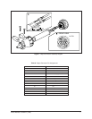
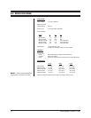
Assemble the connector parts according to the instructions below. Refer to Figure 1
during assembly. For best results use an AMP style crimper when making the wire-
to-pin connection.
1. Slide the connector clamp assembly over the conductor cable. If the diameter
of the conductor cable is such that the rubber boot will slide over it easily then
slide the rubber boot onto the conductor cable at this time. If not, discard the
rubber boot.
2. Prepare the wires from the conductor cable as follows. Refer to Detail A in
Figure 1.
a. Strip at least 1" from the cable jacket to expose the wires. You may need
to strip more from the cable jacket if you have more wires.
b. Strip 1/8" from each wire.
c. Using an AMP style crimper, crimp the wires and their insulation to the
connector pins.
3. Slide the connector pins into the appropriate holes in the connector body until
they snap into place. Refer to Table A for output connector pin assignments,
depending on model and options. Refer to Detail B in Figure 1 for the pin
arrangement.
4. Push the connector clamp assembly (with boot, if used) toward the connector
body. Screw the clamp assembly onto the connector body, being careful not to
disturb the wires.
5. To complete the assembly, attach the appropriate clamp with the screws pro-
vided and tighten.
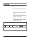
3.2 SYSTEM CONNECTIONS
1. For the rack mount models, install the controller in an appropriate rack.
2. Connect the output cable to the pan and tilt unit and to the rear panel (OUT 1)
of the controller.
3. Connect the 120 VAC, 60 Hz power cord, on the rear panel, to a power recep-
tacle. Some models have an auxiliary AC OUTLET installed on the rear panel
for user convenience.