


Pelco Manual C616M-B (11/97) 5
3.3 RELAY CLOSURE CONNECTIONS
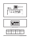
The 6-pin connector (supplied) is used to access a SPDT relay which can be used
to activate a VCR or other devices during an alert. The relay contacts provide a
closure between pins 1 and 3 when an alert condition occurs (see Figure 2, Rear
Panel Controls and Connections).
The relay contact ratings are:
Voltage: 40 VDC or RMS maximum
Current: 0.8 amps DC or RMS maximum (resistive load)
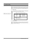
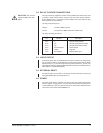
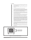
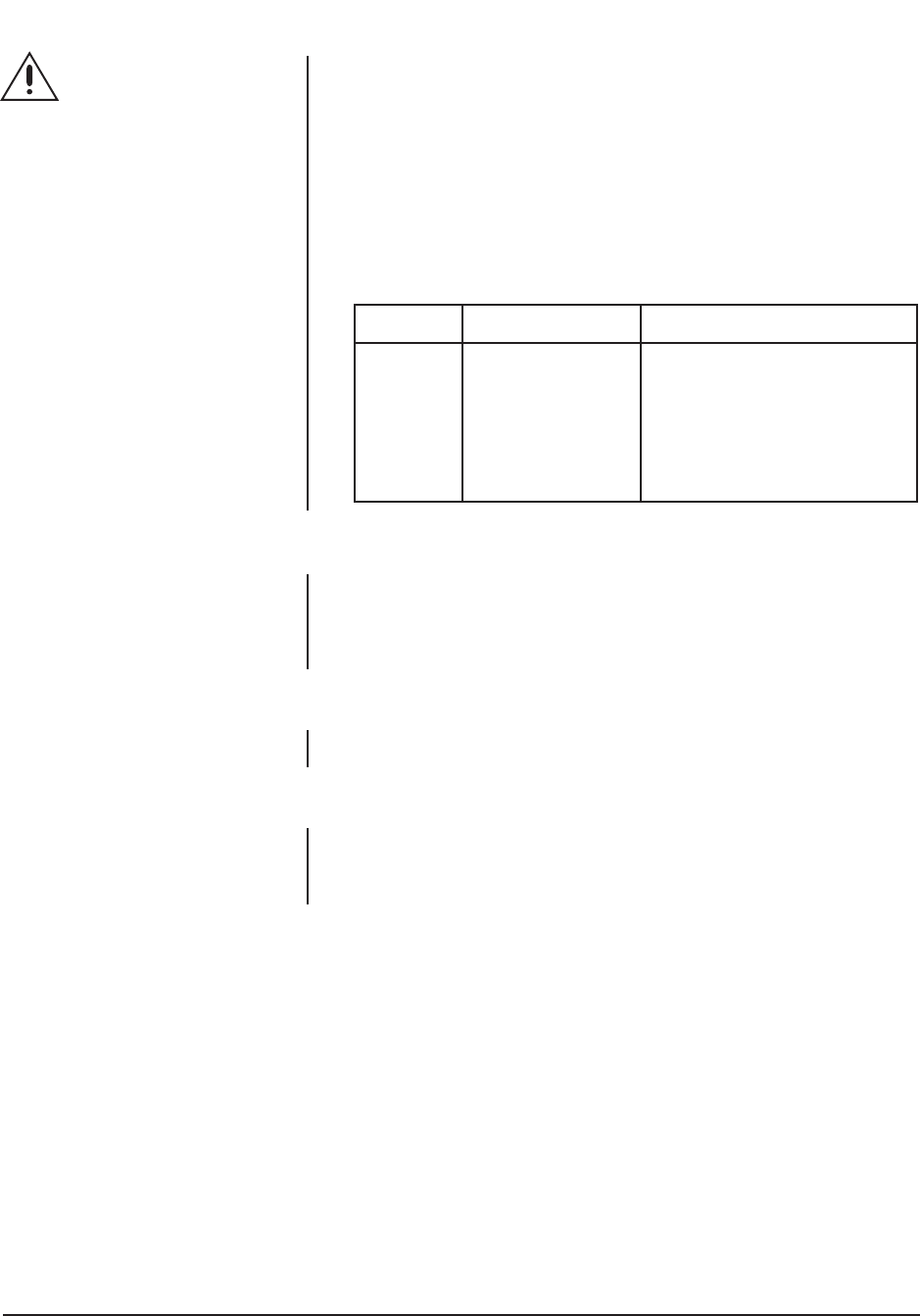
The 6-pin connector pin-outs are:
Pin Function Description
Pin 1 C Common Relay Contact
Pin 2 NC Normally Closed Relay Contact
Pin 3 NO Normally Open Relay Contact
Pin 4 Ground Symbol Circuit Ground
Pin 5 LOGIC Logic Out
Pin 6 EXT RESET External Reset Input
3.4 LOGIC OUTPUT
An external device may be controlled from the 6-pin connector by wiring LOGIC
(Pin 5) and ground (Pin 4). When activated, a ground level signal is at Pin 5. When
inactive, there is a +10 VDC level signal at Pin 5 (referenced to Pin 4, ground). The
logic output should be connected to high impedeance devices; more than 50k ohms.
(See Section 7.0, SPECIFICATIONS)
3.5 EXTERNAL RESET
An external switch can be used as an external reset from the 6-pin connector by
wiring EXT RESET (Pin 6) and ground (Pin 4).
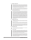
3.6 POWER
No power on/off switch is provided. The LED on the front panel indicates when
power is applied. To apply power: insert the wall mount transformer plug into the
12 VAC PWR jack in the rear panel and insert the wall mount transformer into a
120V power source (230 VAC with MD2001-X).
CAUTION:
Do not use
relays to switch line volt-
ages.