


10. Do one of the following depending on the model number of the enclosure:
• EH3512 Series and EH3515 Series
Connect the heater and defroster wires to the PC board (refer to Figure 2). Be sure the
wires are not obstructing other accessories within the enclosure. If you are installing
HD3515-2 Heater Kit (24 VAC), refer to Table A, 24 VAC Wiring Distances.
• EH3515L Legacy
®
Series
Connect the front and rear heater wires to the HTRS connector (P5) on the circuit board
and the defroster wires to the FAN connector (P4) (refer to Figure 3). You are installing
a lower wattage defroster. You must connect the defroster to FAN (P4) on the PC board
to operate continuously. If you have a blower installed (which is also connected to P4),
splice the defroster wires to the fan wires. If you are installing HD3515-2 Heater Kit
(24 VAC), refer to Table A, 24 VAC Wiring Distances.
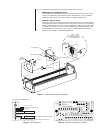
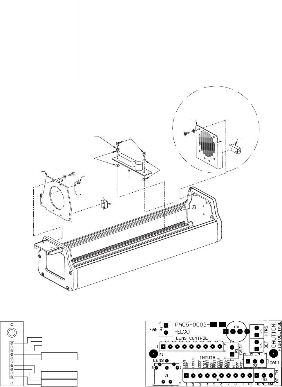
SCREW
LOCK WASHER
NYLON WASHER
PC BOARD
HEATER
DEFROSTER
HEATER
FRONT
HEATER
BRACKET
REAR
HEATER
BRACKET
EH3515 SERIES
AND EH3515L SERIES
ENCLOSURES ONLY
NYLON WASHER
Figure 1. Heater and Defroster Kit Installation
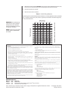
REAR HEATER
1
2
3
4
5
6
7
8
9
10
FRONT HEATER
DEFROSTER
INPUT, AC HIGH
INPUT, AC LOW (NEUTRAL)
GROUND
24/120/230 VAC MODELS
Figure 2. Wiring Diagram
Figure 3. PC Board Component Locations
MODELS HD35 AND HD3515 SERIES
MODEL HD3515 SERIES ONLY