


Pelco Manual C916M (11/90) 3
4.0 INSTALLATION
Refer to the following instructions when installing the
AUX2000 auxiliary control box for the Coaxitron
®
and
Wiretron receiver/drivers.
1. Determine the location for the AUX2000 auxiliary
control box for the Coaxitron
®
or Wiretron receiver/
drivers. To determine the mounting location, con-
sider the distance between the AUX2000 auxiliary
control box for the Coaxitron
®
and Wiretron receiver/
drivers and auxiliary functions used. Attention
should be given to the wire distance table shown
above.
2. Using the AUX2000 auxiliary control box for the
Coaxitron
®
and Wiretron receiver/drivers box as a
template, mount the box to the desired location
using the fasteners (not supplied) which will sup-
port the full load of the unit.
3. Assemble the mating connector as described in
Section 4.1.
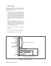
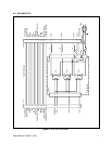
4. Connect the auxiliary device as shown in Figure 1.
5. Plug the AUX2000 into a 120 VAC source.
P/T COMMON
MANUAL IRIS
LEFT
DOWN
UP
RIGHT
GROUND
CAMERA AC (HIGH)
IRIS
FOCUS
ZOOM
LENS COMMON
CAMERA AC (LOW)
AUX 1
AUX 2
AC HI
AUX 3
AC NEUTRAL
1
2
3
5
6
7
8
9
10
11
12
13
14
15
16
18
17
19
FEED THROUGH TO ENCLOSURE
OUTPUT TO A LAMP
OUTPUT TO A MOTOR
RELAY OUTPUT
1
2
3
OUTPUT CIRCUITS ARE RATED FOR 120 VAC,
1 AMP, (120 VA) MAXIMUM EACH
4
Figure 1. Typical Output Circuits