


8 Pelco Manual C505M-B (4/97)
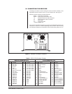
5.0 CX9500 RECEIVER BOARD DESCRIPTIONS
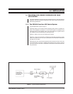
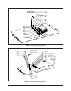
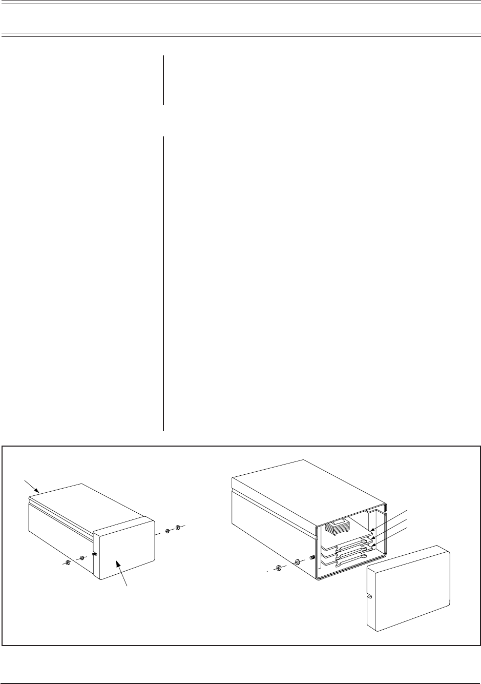
The CX9500 Receiver contains three boards: the Mother Board, the Option Board,
and the Power Supply Board. Gaining access to the board slot locations can be
seen in Figure 5. As part of any operational set-up, the Option and Power Supply
Boards must be pulled and configured. This will be discussed shortly; first, a brief
description of the function of each of the boards is given on the following pages.
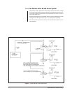
5.1 MOTHER BOARD
The motherboard is the heart of the system. It contains the Microprocessor Cir-
cuits, Video Amplifier Circuits, Sync Generation and Sync Separation circuits and
the Coaxitron Transceiver Circuits.
The Microprocessor Circuit handles all system functions via software interrupts
and communicates with the rest of the circuitry (externally and on the Motherboard
itself) via three functional buss groupings. The first group, the Address/Data buss,
facilitates processor access of external program memory and external data memory.
The second group, the Serial Data buss, among other functions, provides the path
by which the non-volatile EPROMs which contain preset information are accessed
on the Options Board. All data latches and Coaxitron transceiver communications
occur through the third grouping, the External B and C-Data Busses, respectively.
The Video Amplifier and processing circuits add VIS and text bit patterns onto the
camera video or, alternately, removes video from the incoming VIS.
The Sync Generation Circuit, in the presence of a good video signal, separates and
locks the generated sync to the camera. In the absence of a good video signal, the
free running sync from the generator is inserted in place of that from the camera.
The Sync Separation circuit separates the incoming sync from the video informa-
tion and provides the system signal that interrupts the processor every vertical
interval.
The Coaxitron Transceiver Circuits facilitate the storage, error checking and timing
needed to transfer data . The transmitter can send the data to either the coax or the
camera, depending on application. The receiver obtains its input from the last stage
of the video section The receiver amplifies, counts and then gates these data pulses
into temporary Dual Port Ram (DPRAM) storage locations.
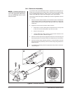
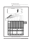
CABLE END
CX9500/9504
TO GAIN ACCESS TO
THE BOARDS WITHIN
THE UNIT, LOOSEN THE
END CAP HARDWARE (NUTS)
AND REMOVE THE END CAP
AS DIRECTED
REMOVABLE
END CAP
POWER SUPPLY BOARD
OPTIONS BOARD
MOTHERBOARD
Figure 5. Receiver Board Locations