


C3425M-D (8/08) 9
Installation
You can install the IS90 Series Camclosure integrated camera system into any of the following:
• Mount to the surface of a ceiling/wall (refer to Surface Installation: Ceiling/Wall on page 9).
• Install in a suspended ceiling (refer to In-Ceiling Installation: Suspended Ceiling on page 11).
• Install in a fixed ceiling/wall (refer to In-Ceiling Installation: Fixed Ceiling/Wall on page 13).
• Mount to the surface of a 4S standard electrical box (refer to Surface Installation: 4S Standard
Electrical Box on page 14).
• Install in a 4S deep electrical box (refer to In-Ceiling Installation: 4S Deep Electrical Box on page 15).
Select the best method for your installation.
UNSHIELDED TWISTED PAIR (UTP) VIDEO
The IS90 Series offers support for unshielded twisted pair (UTP). The UTP video output signal is 1 Vp-p
differential into a 100-ohm load. At a minimum, UTP requires Cat5, 100-ohm twisted pair cable.
SURFACE INSTALLATION: CEILING/WALL
1. Using the template that is supplied, mark the holes on the ceiling/wall for mounting the camera
system and for installing the wiring. Drill the holes. Refer to Figure 3 or Figure 4.
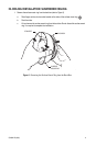
2. Pull video and power wires through the ceiling/wall.
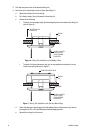
3. Connect the video cable/wires:
• BNC: Connect the BNC connector from the unit to a mating BNC connector.
• UTP: Blue wire = Video +
Gray wire = Video -
4. Connect the power wires.
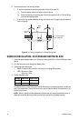
AC operation only: If you are wiring more than one Camclosure to the same transformer, connect one
side of the transformer to the red wire on all units; connect the other side of the transformer to the
black wire on all units.
NOTE: Failure to connect all AC powered units the same way will cause the cameras to be out of
phase with each other and may produce a vertical roll when switching between cameras.
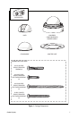
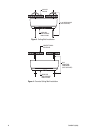
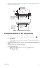
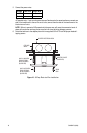
5. For a non-concrete ceiling/wall, use 6-32 toggle bolts to attach the surface mount ring and back box
to the mounting surface (refer to Figure 3). For a concrete ceiling/wall, use 8-32 mounting hardware
(refer to Figure 4). Mounting hardware is not supplied.
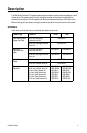
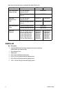
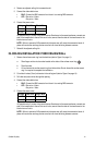
Voltage Red Wire Black Wire
12 VDC + Ground
24 VAC ~ ~