


C3425M-D (8/08) 13
4. Remove an adjacent ceiling tile to access the unit.
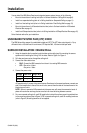
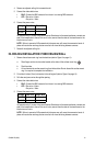
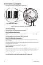
5. Connect the video cable/wires:
• BNC: Connect the BNC connector from the unit to a mating BNC connector.
• UTP: Blue wire = Video +
Gray wire = Video -
6. Connect the power wires.
AC operation only: If you are wiring more than one Camclosure to the same transformer, connect one
side of the transformer to the red wire on all units; connect the other side of the transformer to the
black wire on all units.
NOTE: Failure to connect all AC powered units the same way will cause the cameras to be out of
phase with each other and may produce a vertical roll when switching between cameras.
7. Reinstall the adjacent ceiling tile.
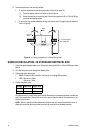
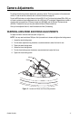
IN-CEILING INSTALLATION: FIXED CEILING/WALL
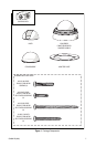
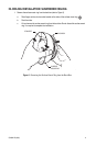
1. Remove the surface mount ring from the back box (refer to Figure 5 on page 11):
a. Place fingers on the circular marks located on the sides of the surface mount ring .
b. Pinch the sides.
c. Lift and remove the surface mount ring from the back box. Do not discard the surface mount
ring; it is required to complete the installation.
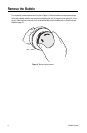
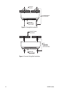
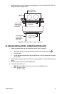
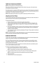
2. Cut a hole 4 inches (10 cm) in diameter in the ceiling/wall (refer to Figure 8 on page 14).
3. Pull video and power wires through the opening.
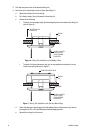
4. Connect the video cable/wires:
• BNC: Connect the BNC connector from the unit to a mating BNC connector.
• UTP: Blue wire = Video +
Gray wire = Video -
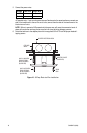
5. Connect the power wires.
AC operation only: If you are wiring more than one Camclosure to the same transformer, connect one
side of the transformer to the red wire on all units; connect the other side of the transformer to the
black wire on all units.
NOTE: Failure to connect all AC powered units the same way will cause the cameras to be out of
phase with each other and may produce a vertical roll when switching between cameras.
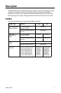
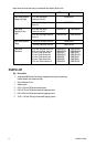
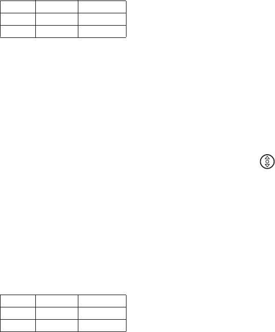
Voltage Red Wire Black Wire
12 VDC + Ground
24 VAC ~ ~
Voltage Red Wire Black Wire
12 VDC + Ground
24 VAC ~ ~