


[ 8 ] Pelco Manual C2915M-E (08/05)
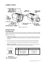
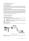
Camera Mounting
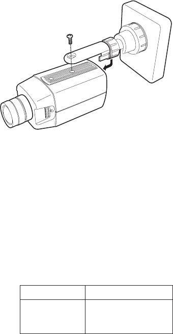
Mounting points are provided on the top and bottom of the camera and are used to mount the camera on a
bracket or tripod. They are designed to accept standard photographic mounting bolts (1/4-inch UNC-20). The
mounting bracket must be capable of supporting the weight of the camera and its lens.
NOTE: Some installation codes dictate that the mounting bracket must be capable of supporting up to four
times the combined weight of the camera and lens.
Figure 3. Camera Mounting
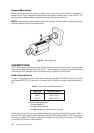
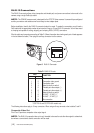
CONNECTIONS
CC3770 Series cameras offer standard power and coax video connectors as well as an RJ45-10 connector that
combines low voltage power and video (coax or UTP). These cameras also have a service connector allowing
a video monitor to be connected locally to the camera using a composite video BNC cable.
Video Connections
To obtain a video output, connect a video coaxial cable terminated with a 75Ω BNC connector to the BNC
socket marked VIDEO OUT on the rear of the camera. Refer to Table A for the type of video coaxial cable to
use.
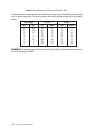
Table A. Video Coaxial Cable Requirements
Cable Type* Maximum Distance
RG59/U 750 ft (229 m)
RG6/U 1,000 ft (305 m)
RG11/U 1,500 ft (457 m)
* Minimum cable requirements:
75 ohms impedance
All-copper center conductor
All-copper braided shield with 95% braid coverage
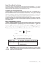
Another way to transmit video is over unshielded twisted pair wiring through the RJ45-10 connector. Refer to
the RJ45-10 Connections section. When outputting composite video through the BNC or RJ45-10, do not send
UTP output to a passive UTP receiver. However it is acceptable to use an active UTP receiver for UTP output
in combination with the other video connections.