


C2495M-A (1/06) 7
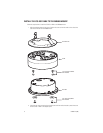
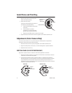
3. Do the following to install the back box inside the cover of the ICS-DO111ABK:
a. Feed the video cable and power wires attached to the ICS-DO111ABK back box through
the cover and adapter plate of the ICS-DO111ABK.
b. Rotate and position the back box so that the conduit plug on the side of the box is
located on the opposite side (180 degrees) from the notch on the side of the cover.
Use the supplied 8-32 x 0.375-inch screws and washers to secure the back box to the
cover.
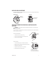
4. Connect the power wires:
•
For 12 VDC, connect the 24 VAC/12 VDC (red) and GND (black) wires to input power.
The blue wire is not used.
•
For 24 VAC, connect the 24 VAC/12 VDC (red) and 24 VAC (blue) wires to input power.
The black wire is not used.
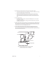
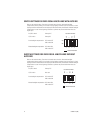
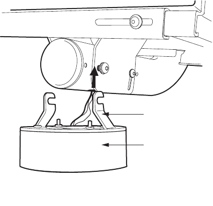
5. Feed the video connector from the Camclosure
®
base through the ICS-DO111ABK feedthrough
hole in the mount and out the bottom of the mount arm. Connect the video connector to the
mating connector of the video cable. Push the video cable back into the mount arm, and then
reinstall the bottom end cap of the MR5000 Series mount.
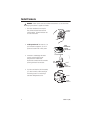
6. Use the supplied 3/16-inch Allen wrench and slightly loosen (do not remove) the two
5/16-18 x 0.750-inch Allen pan head screws that secure the MR5000 mount base to the
mount arm. Hook the adapter plate and cover over the loosened screws. Tighten the screws to
secure the adapter plate to the mount.
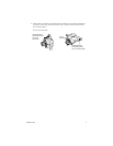
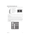
ADAPTER PLATE
CAMCLOSURE BASE
NOTE: POSITION THE BASE SO THAT THE CONDUIT OPENING
IS TURNED TOWARD THE BACK OF THE MOUNT.