


4 C2493M (12/05)
4
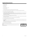
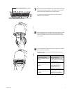
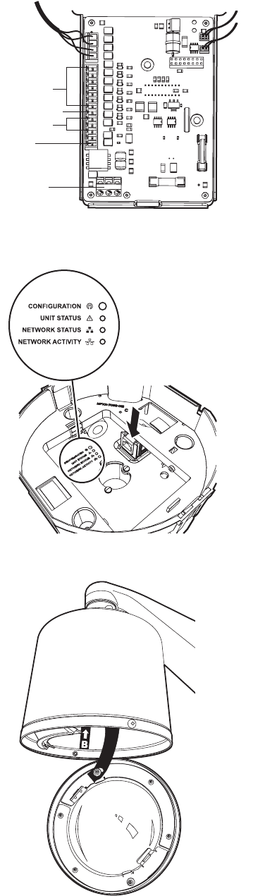
Connect the power wires to the circuit board inside the back box.
Connect any alarm and auxiliary circuits. Turn on the power to the
system. The green LED on the door indicates system power is on.
NOTE: Aux 1 – Maximum 2 A at low voltage (<40 V)
5
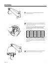
Connect a 10/100/1000BaseT network Cat5e (or better) cable to the
RJ-45 network connector located inside the back box. Check the LED
indicators located inside the back box to check unit status, network
status, and network activity.
Unit Status LED
Green Unit is functioning normally.
Amber Unit is in configuration mode.
Red Unit is in an error condition.
Network Status LED
Off Unit is not connected to the network.
Amber Unit is connected to a 100BaseT network.
Red Unit is connected to a 10BaseT network.
Network Activity LED
The LED flashes whenever the unit is sending or receiving network data.
6
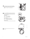
Close the door to the back box. Attach the back box leash to the
lower dome.
ALARMS
ALARM COM
AUX1
AUX COM
POWER