


[
4
]
Pelco Manual C1992M-A (12/03)
INSTALLATION
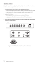
The monitor may be placed on any flat surface (desk or table) or rack-mounted. To rack-mount the moni-
tor follow the instructions supplied with the rack-mount kit.
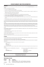
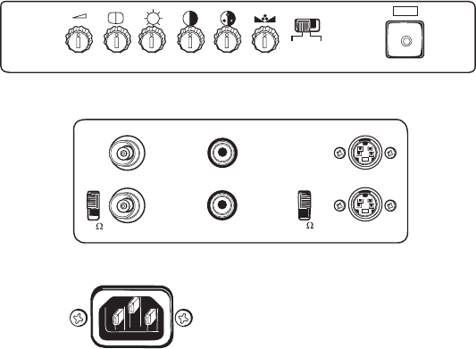
1. Video Cable Connection (Refer to Table A for video coaxial cable requirements.)
a. Connect the video cable to the BNC video input labeled V1 IN on the back panel of the monitor.
b. Looping Operation Only - Connect a video cable to the BNC connector labeled V1 OUT.
2. Impedance Switch Setting
a. Terminating Operation Only - Set the termination switch to the 75W position.
b. Looping Operation Only - Set the impedance switch to the Y/C-HI position (looping).
3. Plug the power cord (provided) into the AC INLET connection on the back panel. Plug the other end
of the cord into a power receptacle.
V1-HI
V1 OUT
V1 IN AU1 IN
AU1 OUT
Y/C-HI
75
S-VIDEO IN
S-VIDEO OUT
VOLUME SHARP BRIGHT CONT. COLOR TINT
VIDEO
FRONT
BACK
AC INLET
S-VIDEO
75
Figure 1. Model PMC10A, 10-inch Color Monitor, Front and Back Panels