


PELCO Manual C436M-B (12/94) 3
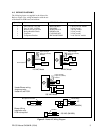
Figure 2. Blower Kit Wiring Diagram
Input, AC High
Input, AC (neutral)
Ground
Fan
Heater
1
2
3
4
5
6
7
8
9
10
120 VAC Model
Input, AC High
Input, AC (neutral)
Ground
Heater
1
2
3
4
5
6
7
8
9
10
Diode
Bridge
24 VAC Model
230 VAC Model
Input, AC High
Input, AC (neutral)
Ground
Fan
1
2
3
4
5
6
7
8
9
10
Heater
Heater
Heater/Blower wiring
diagrams using
Heater Kit with PCB.
120 VAC (BK4000)
Fan
Fan
Fan
Butt Splices Provided
Resistor
230 VAC (BK4220)
Diode Bridge
Thermostat
Blower Wiring
Installation only.
PCB not required.
Fan
Cap
24 VAC (BK4024)
Cap
Resistor
4.0 WIRING DIAGRAMS
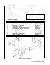
The following items are supplied in the blower kits.
Refer to Figure 2 for wiring information with the use
of the heater kit PCB board, and without.
Quantity Item PELCO Part No. Blower Kit
1 Fan, 120 VAC, 19 CFM MM750010003 120 & 230 VAC models
1 Fan, 24 VDC, 19 CFM ED210005 24 VAC model
1 Resistor for fan, 3K ohm RES003.0K10.0 230 VAC model
1 Bridge Rectifier Diode DIOMDA104 24 VAC model
1 Capacitor CAPU0050.0/25 24 VAC model
1 Component Bracket BK7044002COMP 24 & 230 VAC models
AC
+
_