


2 PELCO Manual C436M-B (12/94)
3.0 INSTALLATION
The BK4000/BK4024/BK4220 Blower Kits are sup-
plied with the following installation parts:
QTY ITEM
1 Blower
1 Blower Bracket
To install the BK4000/BK4024/BK4220 perform the
following steps (refer to Figure 1):
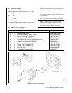
Figure 1. Blower Kit Installation
1. Remove the Phillips Head screws from the rear cap
and slide the assembly out from the enclosure.
2. Attach the blower assembly to the rear plate using
two of the self-tapping screws, holding the end
cap to the sled.
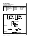
3. Wire according to the wiring diagram in Figure 2.
NOTE: When used with a heater kit (and
PCB), the blower can be wired into the termi-
nal block on the PC Board (see Figure 2). With
the blower kit only, the PCB is not necessary.
3.1 PARTS LIST (Figure 1.)
Item Qty Description Part Number
1 1 Bracket, fan/pc board BK40004000COMP
2 1 Bracket component, 24VAC, 230VAC BK7044002COMP
1 PCB assy, term/thermott, (used with heater kit) PCB9000300ASSY
3 1 Fan, 2.36-inch Sq., 120/230 VAC MM750010003
1 Fan, 2.36-inch Sq., 24VDC ED210005
4 1 Resistor 3k ohm, 10w (230 VAC blowerkit only) RES003.0K10.0
1 Diode Bridge Rect, 1A400PRV (24 VAC only) DIOMDA104
5 1 Insulator, PC board (heater kit only) BK400010000
A 4 Washer, nylon ZH200X437X62N
B 4 Screw, 6-32 x 3/8 pan phil SS ZH6-32X.375SPP
C 2 Screw, 6-32 x 1.5 pan phil SS ZH6-32X1.50SPP
D 2 Nut, hex, 6-32 ZH6-323NUTSH
E 2 Screw, 6-32 x 1/4 self tapping phil ZH6-SFX.250SPP
F 8 Internal tooth lockwasher, #6 ZH6LWSIS