


7 of 7
ISSUED: 04-27-05 SHEET #: 201-9421-10 10-27-09
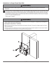
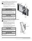
Attach screen to tilt assembly (B). Tighten M5 x 6
mm screw (H) to lock screen to tilt assembly.
Note: For security models, use security driver (I) to
tighten M5 x 6 mm screws (H).
To remove screen from mount, loosen screw (H) and
lift screen off of mount.
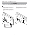
Installing and Removing Flat Panel Screen
3
• Do not lift more weight than you can handle. Use
additional man power or mechanical lifting equipment
to safely handle placement of the screen.
• Failure to lock adapter plate (A) with screw (H) can
cause screen to come off mount if hit accidentally.
• Do not tighten screws with excessive force.
Overtightening can cause damage to mount. Tighten
screws to 20 in. • lb (2.26 N.M.) maximum torque.
CAUTION
WARNING
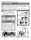
Adjust tension knob on right side of mount shown in
figure 4 to desired tension to balance your screen
size and weight.
Note: If knob is inaccessible, remove screen from
mount, adjust tension knob to desired tension to
balance your screen size and weight, and reattach
screen to mount as stated in step 3.
Push or pull from top or bottom of screen to adjust
tilt as shown in figure 4. The tilt can be adjusted to a
maximum of 15° forward or 5° backward.
4
Adjusting the Tilt Angle of the Flat Panel Screen
• Be careful not to pinch fingers when pushing screen
from the bottom.
CAUTION
• Do not tighten screws with excessive force.
Overtightening can cause damage to mount. Tighten
screws to 40 in. • lb (4.5 N.M.) maximum torque.
CAUTION
fig. 4
TENSION KNOB
A
SCREEN
H
B
fig. 3
© 2007, Peerless Industries, Inc. All rights reserved.
All other brand and product names are trademarks or registered trademarks of their respective owners.