


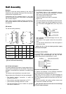


5
Unit Assembly
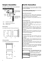
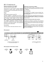
Brackets
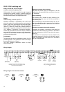
Brackets for wall and ceiling assembly (2 per unit) are
inserted into the openings at the back of the unit and at-
tached with the supplied screws.
Components that are attached directly to the units,
such as mixed-air boxes or filter boxes, are equipped
with a bracket adapter.
When using customer-installed bracket constructions,
the minimum distance to the wall (dimension "e") must
be observed!
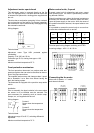
KO bracket
For wall and ceiling assembly
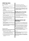
Cu / Al heat-exchangers
The heat-exchangers are made of copper pipes with alu-
minium plate fins pressed onto the outside. The plate fin
package is surrounded by a galvanized, zinc-plated steel
frame.
The collector and the distributor are made of steel.
Please observe the following for the heat-exchangers:
◊ The heating medium connection is made via
threaded connectors.
◊ The maximum operating temperature is 130 °C.
◊ The maximum operating pressure is 16 bar.
◊ The heat-exchangers are not suitable for operation
with steam or thermal oil.
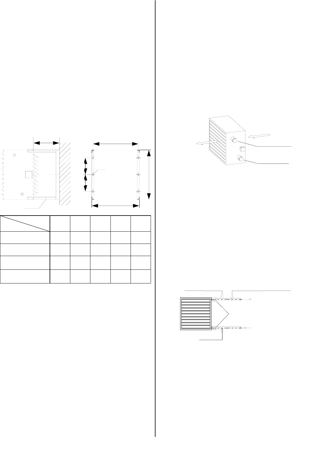
Connection to the heating system
◊ The REMKO PWW is to be connected by the cus-
tomer via the shut-off valve, automatic air bleeder
and screws in the supply and return lines.
Use compensators if necessary.
◊ It does not matter which side is connected.
Right or left.
◊ The units operate on the principle of counter-current.
◊ The water (supply line) usually comes in at the bot-
tom. The water usually goes out (return line) at the
top.
Draining in case of frost
It is not possible to statically drain the heat-exchanger
completely. The heat-exchanger can only be com-
pletely drained when compressed air is used.
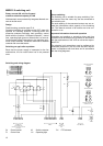
Drainage
Ventilation Frost protection thermostat
Screws
Incoming air
Outgoing air
Incoming water
Outgoing water
PWW
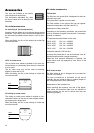
Dimension
a b c d
4030-3 / 4 560 430 510 155 270
4050-3 / 4 640 505 590 192 270
4080-3 / 4 800 620 750 250 270
4100-3 / 4 880 730 830 305 340
e
The brackets must be current-free and screwed on
to the unit and the wall/ceiling.
◊ After assembly, the heat-exchanger must be care-
fully ventilated.
Air pockets in the register reduce the unit perform-
ance.
◊ You can find the thread sizes of the heat register in
the technical data.
When the fan is idle, the heating medium supply
must be interrupted.
Important information about frost protection!
To prevent frost damage, a frost protection mechanism
must be attached for temperatures below 0 °C.
There may not be any water in the heat-exchanger for
systems taken out of operation in rooms susceptible to
frost. The remaining water must be blown out with com-
pressed air.
If this is not possible, the heating medium (water) must
be mixed with a suitable anti-freeze.
No guarantee claims can be made for frost damage
on the heat-exchanger!
KO
e
c
a
b
d
d
Ø12.5