


12
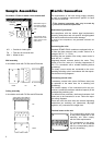
MSRD 2.5 switching unit
Rotary current 400 volt, fan 2-speed
maximum electrical capacity 2.5 kW
Wall-mounted, motor protected by integrated thermal con-
tacts in the fan motor.
Design
Plastic housing, protection type IP 41.
Protective insulation in accordance with VDE, plate with
symbols for switching positions, incoming power and
protective conductor terminals, main contactor, control
switch with the functions “Off/Speed 1/Speed 2”, control
fuse, operating light (goes out when there is a fan mal-
function and/or power interruption to the switching unit),
motor output terminals, connection terminals for thermal
contacts and room thermostat.
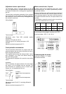
Switching on again after a problem
Each time the power supply is interrupted or the fan
malfunctions, the fan reset button has to be pressed
once.
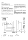
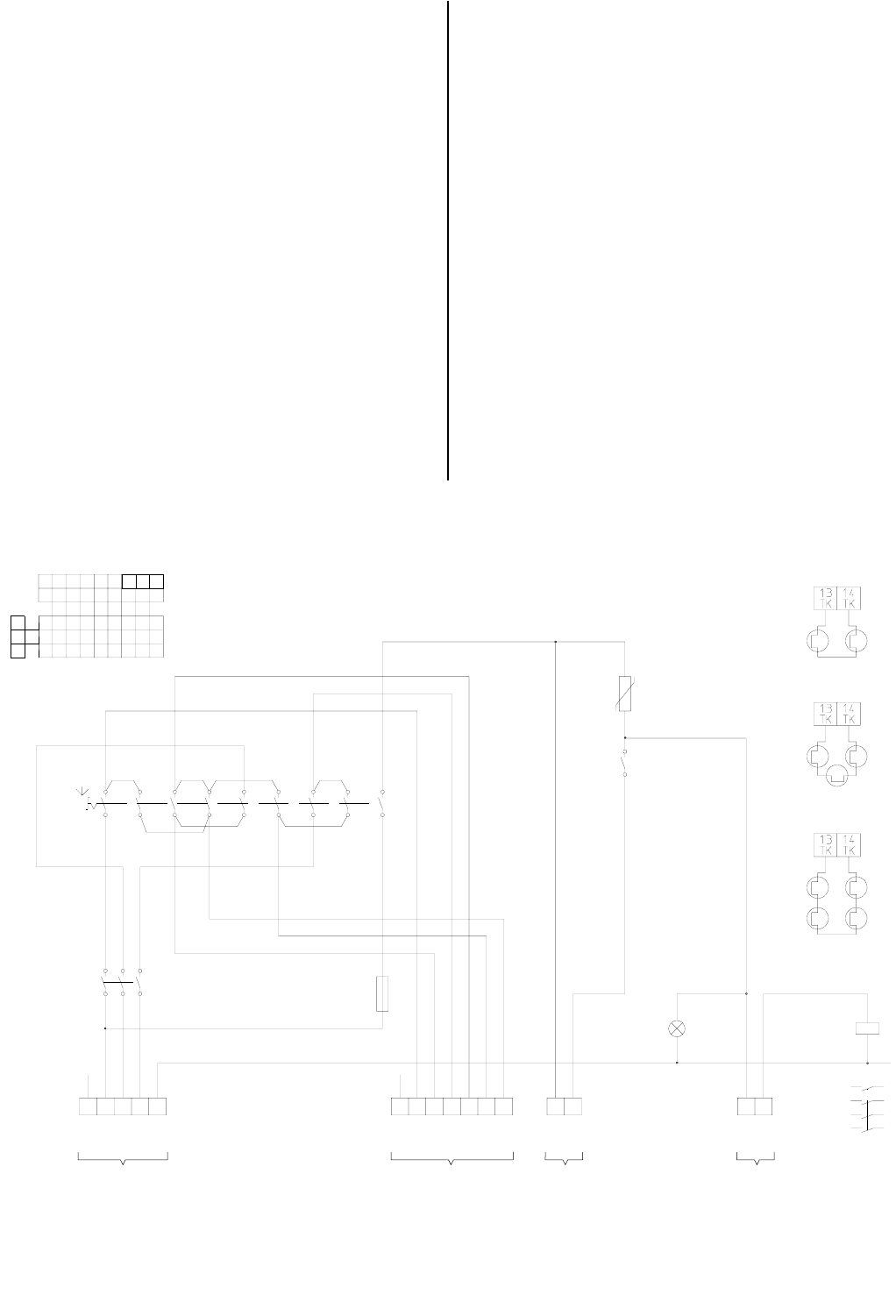
Switching and wiring diagram
1 3 5 7 9 11 13 15 17
2 4 6 8 10 12 14 16 18
X X X
X X X X
X X X
X X X
0
D
U
0
D
U
1
2
3
4
7
8
9
10
11
12
13
14
15
16
17
18
5
6
S1
R1
K1
13
14
K1
1 3 5
2 4 6
F1
6,3A
H1
X1
X2
K1
A1
A2
2 3 4
PE L1 L2 L3 N
1 5
7 8 9 6 10 11 12 13
PE U1 V1 W1 U2
V2 W2
TK TK
14
15
RT RT
16
4
4
4
11
1
3
5
13
2
4
6
14
Room thermostat Thermal
contacts in the
motor
Incoming power
400V/3/N/PE 50HZ
Grounding in accordance with local
requirements
Motor 3~
Thermal protections
for 2 units
Thermal protection
for 3 units
Thermal protection
for 4 units
Connect other thermal
contacts in a row
S1 Control switch K1 Switch contactor R1 PTC element
F1 Control fuse H1 Operating light
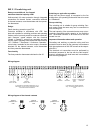
Group switching
The switching unit is suitable for group switching. Sev-
eral motors wired the same way can be connected to
one switching unit.
The total capacity of the connected motors may not ex-
ceed the permissible switch capacity of the switching
unit. The thermal contacts of all motors are to be con-
nected in a row.
Important information about safe operation
Grounding and earthing or protective wiring and fuse
protection must be done by the customer in accordance
with the requirements of the VDE as well as the respon-
sible EVU.
The electrical unit connections must be performed by
authorised personnel in the line with the valid require-
ments in compliance with local laws and in accordance
with the wiring diagrams.