


- 4 -
WJ-HD316A
WU-CU650
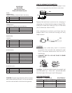
Wiring Color Code
Power and Control Inputs
1 24 VAC Live Black
2 24 VAC Live White
3 Green Green
4 Not Used
1 24 VAC Live Red
2 24 VAC Live White
3 Green Green
4 Not Used
1 Ground Brown
2 TXB (RS485) Red
3 TXA (RS485) Orange
4 RXB (RS485) Yellow
5 RXB (RS485) Green
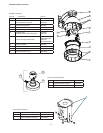
CAMERA POWER [13 watts WV-CS954 / WV-CS574]
CONNECTOR B
ACCESSORY POWER [52 watts Heater/Blower]
CONTROL
POD9C
CONNECTOR A
Pan/Tilt Unit Only
1 Alarm In 1 Black
2 Ground Brown
3 Alarm In 2 Red
4 Ground Orange
5 Alarm In 3 Yellow
6 Ground Light blue or green
7 Alarm In 4 Blue
8 Ground Purple
ALARM IN (8-pin)
1 Alarm Out 1 Gray
2 Ground White
3 Alarm Out 2 Pink
4 Ground Yellow, Green, or Light blue
ALARM OUT (4-pin)
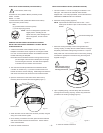
Approx. 0.1"
Wire
Insert
Up
Contact
Wire
Up
Contact
1
2
4
3
1
2
4
3
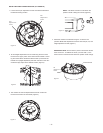
HOW TO ASSEMbLE THE CONNECTOR
• Strip back the cable jacket approximately 0.1 inch
(3 mm) and separate the individual conductors.
Prepare the individual conductors for clamping. If
clamping, use Molex brand tool part number 57027-
5000 (for UL-listed-style cable UL1015) or 57026-5000
(for UL-listed-style cable UL1007).
After clamping the contacts, push them into the
proper holes in the connector housing until they
snap in place.
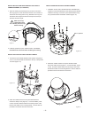
CAUTIONS
• Shrinking the cable-entry seal is a onetime
procedure. Do not shrink the cable-entry seal
until it has been determined that the unit is
functioning.
• CONNECT THIS TO A 24 VAC CLASS 2 POWER
SUPPLY ONLY.
CAUTION: TO PREVENT FIRE OR SHOCK HAZARD, THE
UL-LISTED WIRE VW-1, STYLE 1007, SHOULD BE USED
FOR THE CABLE FOR 24 VAC INPUT TERMINALS.
OPERATING DISTANCES
Awg Size Impedance Max Distance
Awg #12 1.71 ohm/1000 ft. 440 ft.
Awg #14 2.73 ohm/1000 ft. 270 ft.
Awg #16 4.35 ohm/1000 ft. 170 ft.
Awg #18 6.92 ohm/1000 ft. 100 ft.
CAUTION: For lightning protection of the camera
and heater/blower, the pin 3 of the connector
must be connected to real electrical ground.