


MC-V414 00
12
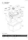
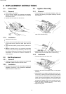
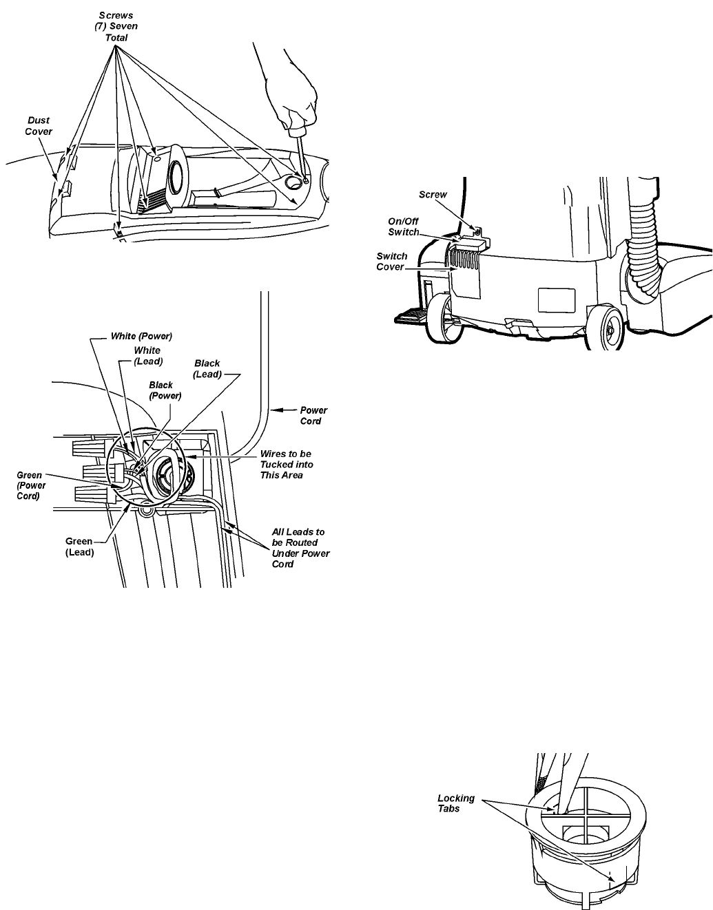
3.5. Power Cord Replacement
3.5.1. Removal
1. Remove the seven (7) screws that secure the dust cover
and remove the dust cover.
2. Remove the two (2) wire connectors, disconnect the
wires and pull the cord from the back of the unit.
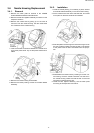
3.5.2. Installation
1. Insert the new cord into the dust container and wrap
around the strain relief as shown above.
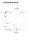
2. Rewire per the wiring diagram and secure using the two
(2) wire connectors that were removed earlier.
3. Route all wiring according to the wire management draw-
ing shown earlier in this manual.
4. Install the dust cover by first ensuring all wiring are routed
correctly so that no wires may be pinched during
assembly.
NOTE: For general servicing, it is necessary to eliminate pinch-
ing of any wire during reassembly. After servicing any electrical
component or electrical enclosure, the unit should be reassem-
bled and checked for dielectric breakdown or current leakage.
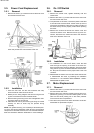
3.6. On / Off Switch
3.6.1. Removal
1. Remove the nozzle cover, agitator assembly, belt and
nozzle base.
2. Remove the seven (7) screws that secure the dust cover
and remove the dust cover.
3. To replace the on-off switch, remove the plastic insert that
is mounted over the motor shaft. Lift the motor up and out
of the dust compartment. Take care to note the position of
the wires so they can be properly tucked when replacing
the motor.
4. Remove the screw that secures the switch cover and
remove the switch cover. Remove the two (2) wire con-
nectors, disconnect the switch lead wires and slide the
wires out of the back of the unit.
3.6.2. Installation
1. For installation of a new on-off switch, insert the lead
wires through the opening in the back of the dust con-
tainer and rewire per the wiring diagram. Secure the wires
using the two (2) wire connectors that were removed ear-
lier. Snap the new switch into the proper slots in the dust
container.
2. Reassemble the switch cover and the screw that secures
it. Reassemble the motor by following the installation
instructions in the MOTOR REPLACEMENT section.
Reassemble the plastic insert.
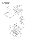
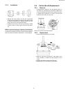
3.7. Motor Replacement
3.7.1. Removal
1. Remove the seven (7) screws that secure the dust cover
and remove the dust cover.
2. Remove the motor protector located inside the dust com-
partment by pushing in on the two retaining tabs. Do one
side at a time while pushing out on the motor protector
from inside the dust compartment.
3. Once the motor protector has been removed it can be dis-
assembled for replacement of parts.