


Red to
wall switch
Blue to
wall switch
Brown to
wall switch
Green to earth
ground
Wire nut
White to neutral
Black to live
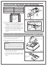
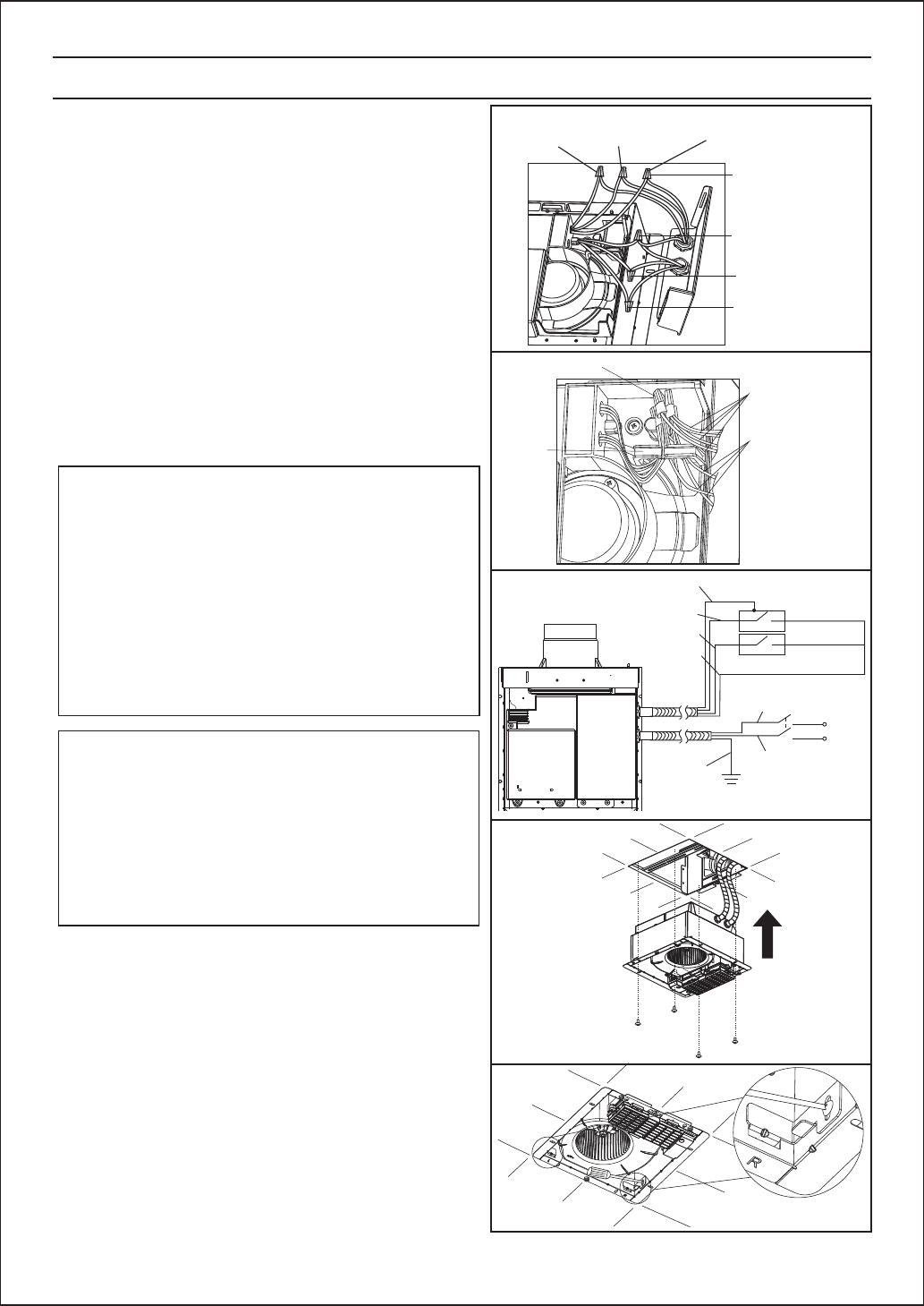
INSTALLATION JOIST MOUNTING-Ⅰ) CONTINUEDⅠ(BETWEEN
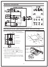
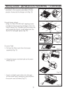
③ Refer to wiring diagram (Page.6) or Fig.9,
follow all the local electrical safety codes.
As well as the National Electrical code
(NEC),Using UL approved wire nuts,
connect house power wires and control
lead wires to product wires.(Fig.7)
Make sure all connections are fastened
firmly after wiring is finished.
8
For future inspection by qualified persons,
put the lead wires into the hook after
connection work.
④
(Fig.8)
Fig.7
Fig.8
Wire nut
Control
lead wines
Power
wires
Hook
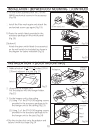
HEAT/VENT
Fig.9
From red wire
From blue wire
From brown wire
(wall switch)
Green wire
White
ON/OFF
Black
E
N
L
Green
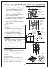
⑤ Fix the cord cover with the screws that
taken off at step1.
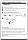
1. Disconnect power source before working
on unit.
2. When making wiring connections take
care to prevent excessive slack in the
wiring since a layge of current is drawn
through the heater electrical wire.
3. To reduce the risk of fire, do not store or
use gasoline or other flammable vapors
and liquids in the vicinity of the heater
WARNING
1.High temperature, risk of fire, keep electrical
cords, drapery,furnishings, and other
combustibles at least 3 feet (0.9 m) from the
front of the heater and away from the side
and rear.
2.Mount the cord cover carefully so that lead
wires are not pinched.
CAUTION
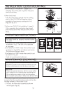
6. Main body fixed.
Push the main body upward into the ceiling,
use 4 of the ST4.2X30self-tapping screws
provided in the accessory package to fix it.
(Fig.10)
7.Install plate fixed.
Insert the install plates into the main body
jockey for position(one of each side), use the
ST4.2X10 self-tapping screws provided in the
accessory package to fix them. (Fig.11)
Fig.10
Fig.11