


200
EQ-500
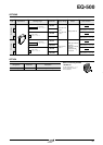
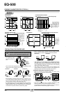
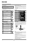
SENSING CHARACTERISTICS (TYPICAL)
Sensing fields
• Setting distance: 0.5 m 1.640 ft
This curve shows
the characteristics
with the maximum
sensing range set
to 1 m 3.281 ft,
with white non-
glossy paper
(200
ן200 mm
7.874
ן7.874 in).
Emitted beam Correlation between sensing object size
and sensing range
0.5
1.640
1
3.281
White non-
glossy paper
Sensor
L
20 10 0 10 20
0
0.5
1.640
1
3.281
L
?
Sensor
EQ-502(T)
EQ-512(T)
• Setting distance: 1 m 3.281 ft
0
0
0.2
0.656
0.4
1.312
0.6
1.969
0.8
2.625
L
?
Black non-glossy paper
Lightness: 5
Black non-glossy paper
Lightness: 5
0
0.5
1.640
1
3.281
Correlation between material
(200
200 mm 7.8747.874 in) and sensing range
These bars indicate the
sensing range with the
respective objects when
the distance adjuster is set
to a sensing range of 1 m
3.281 ft / 0.5 m 1.640 ft
long, respectively, with
white non-glossy paper.
Correlation between color
(200
200 mm 7.874
7.874 in non-glossy paper) and sensing range
These bars indicate the
sensing range with the re-
spective colors when the
distance adjuster is set to a
sensing range of 1 m 3.281 ft
/ 0.5 m 1.640 ft long,
respectively, with white non-
glossy paper.
The sensing range also
varies depending on material.
0.5
1.640
1
3.281
20
0.787
10
0.394
10
0.394
20
0.787
020
0.787
10
0.394
10
0.394
20
0.787
200
ן
200 mm
7.874
ן
7.874 in
Non-glossy paper
200
ן
200 mm
7.874
ן
7.874 in
Non-glossy paper
Sensor
⅐⅐⅐
⅐⅐⅐
⅐⅐⅐
⅐⅐⅐
0
1
3.281
0.5
1.640
Distance L (m ft)
White non-glossy paper
side length a (mm in)
"26 mm
"1.024 in
"20 mm
"0.787 in
White non-
glossy paper
White non-
glossy paper
Left
Right
Center
Operating point ?(mm in)
Left
Right
Center
Operating point ?(mm in)
Setting distance L (m ft)
Setting distance L (m ft)
Sensing range L (m
ft)
Sensing range L (m
ft)
Sensing range L (m
ft)
1 m
3.281 ft
0.5 m
1.640 ft
White non-
glossy paper
Cardboard
Plywood
Black rubber
Black non-grossy
paper (Lightness: 5)
White
Yellow
Orange
Red
Brown
Blue
Green
Gray
(Lightness: 8)
Black
(Lightness: 5)
1 m
3.281 ft
0.5 m
1.640 ft
050
1.969
100
3.937
150
5.906
200
7.874
Setting distance: 1 m 3.281 ft
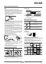
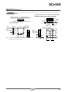
PRECAUTIONS FOR PROPER USE
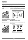
Mounting
Sensing object
Sensing object
Do not make the sensor
detect an object in this
direction because it may
cause unstable
Sensing object
Tilt
Interference
prevented area
L mm in
or more
L mm in
or more
L mm in
or more
1
3.281
2
6.562
3
9.843
060
2.362
20
0.787
80
3.15
40
1.575
Mounting interval L (mm in)
Setting distance (m ft)
Setting distance (m ft)
Mounting interval L (mm in)
1
3.281
2
6.562
3
9.843
0
150
5.906
250
9.843
50
1.969
200
7.874
100
3.937
Interference
prevented area
This product is not a safety sensor. Its use is not
intended or designed to protect life and prevent body
injury or property damage from dangerous parts of
machinery. It is a normal object detection sensor.
•
The tightening torque
should be 0.8 N⅐m or
less.
•
Care must be taken regarding the sensor mounting direction with
respect to the object’s direction of movement.
Sensor
mounting
blacket
MS-EQ5-01
(Optional)
M5 nut
M5 (length 30 mm 1.181 in)
screw with washers
•
•
When detecting a specular object (aluminum or copper foil, etc.)
or an object having a glossy surface or coating, please note that
there are cases when the object may not be detected due to a
change in angle, wrinkles on the object surface, etc.
If a specular body is present in the background, faulty operation
may be caused due to a small change in the angle of the
background body. In that case, install the sensor at an inclination
and confirm the operation with the actual sensing object.
•
When a specular body is present below the sensor, use the
sensor by tilting it slightly upwards to avoid faulty operation.
Specular
face
Specular
face
•
•
This product is not easily affected by the reflected light intensity
since this sensor is the adjustable range reflective type. When
the reflected light intensity is remarkably low, the sensing range
may be affected. In that case, mount the sensor, while checking
light-up of the stable indicator (green).
The mounting screws of the terminal cover and display cover
should certainly be tightened to maintain water-resistance; the
tightening torque of the screws should be 0.3 to 0.5 N⅐m.
Automatic interference prevention function
•
When the sensors are mounted closely, use them in the
interference prevented area, as shown below.
•
Note that the detection may be unstable depending on the
mounting conditions or the sensing object to be used.
In the state that this product is mounted, be sure to check the
operation with the actual sensing object to be used.
L mm in
or more
<Correct><Correct><Incorrect>
<
Incorrect><Correct>
08/2005