


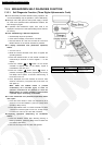
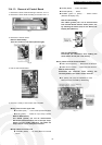
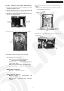
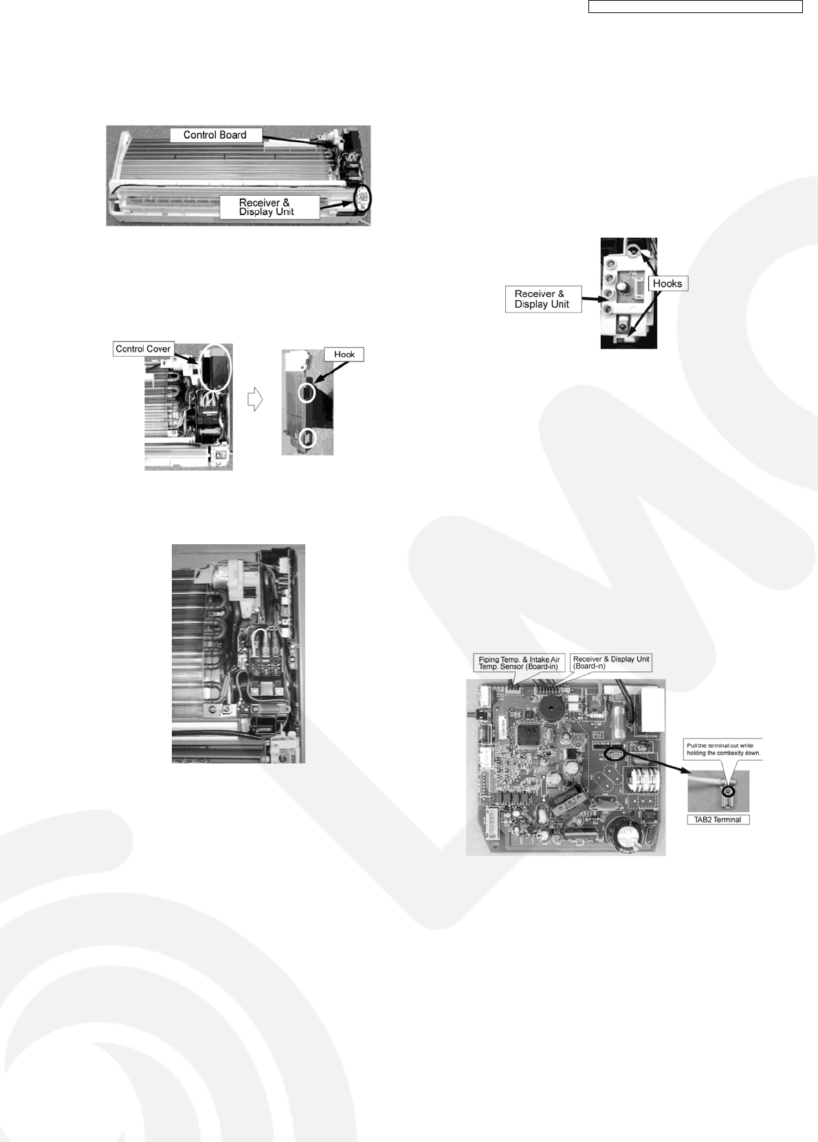
13.4.1.3. Removal of Control Board
1. Remove the Front Panel according to the item 13.5.1.1.
2. Remove the Front Grille according to the item 13.5.1.2.
Fig. 7
3. Remove the Control Cover.
Note for Disassembly:
There are hooks on both sides (left and right).
Fig. 8
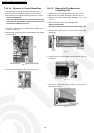
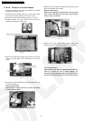
4. Pull out the Control Board.
Fig. 9
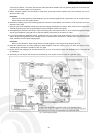
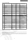
5. Remove a variety of Connectors and Terminals.
Wiring parts from the upper side
•
• •
•
CN-STM2 (blue) ...... Front Panel Open/Close Motor
•
• •
•
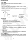
CN-TH (yellow) ...... Intake Air / Pipe Temp. Sensor
Note for Disassembly:
The CN-TH (yellow) can not be disconnected.
Disconnect thermosensitive part of the Pipe Temp.
Sensor from the holder (Board-in). The Intake Air
Temp. Sensor can be easily disconnected.
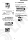
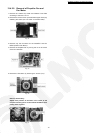
Wiring cables from lower side
•
• •
•
CN-STM1 (White) ...... Air Swing Motor for Vertical
Louver
•
• •
•
CN-FM (White) ...... Indoor Fan Motor
•
• •
•
CN-ION (White) ...... Ionizer
•
• •
•
CN-DISP (green or yellow) ...... Control Board
(Receiver & Display Unit)
Note for Disassembly:
The CN-TH (yellow) can not be disconnected
from Control Board. Remove whole plastic part
by releasing the hooks (two) for the Receiver &
Display Unit (Board-in).
Fig. 10
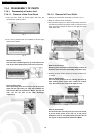
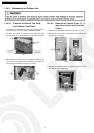
Note for Disassembly:
Disconnect the connectors while holding the
hooks down. Do not pull it out directly.
Wiring cables from the Terminal Board
•
• •
•
TAB1 terminal (brown) ...... Disconnect the terminal.
•
• •
•
TAB2 terminal (white) ...... Disconnect the terminal.
Note for Disassembly:
Disconnect the terminals while holding the
convexity down in the center of each terminal.
•
• •
•
H1 (black), H3 (red) are soldered on PCB. .........
Remove it from the PCB by desoldering.
Fig. 11
67
CS-TE9DKE CU-TE9DKE / CS-TE12DKE CU-TE12DKE