


25
1
2
3
1
2
3
1
2
3
1
2
3
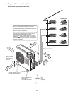
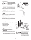
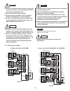
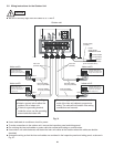
Indoor unit B
Indoor unit A
Ground
Power:
Single-phase,
230/208VAC 60HZ
Power breaker
(not provided)
Outdoor unit
Terminal board
Label A
Inter-unit cables
#14 (not provided)
Terminal board
Inter-unit cables
#14 (not provided)
Terminal board
Label B
Label C
Inter-unit cables
#14 (not provided)
Inter-unit cables
#14 (not provided)
Terminal board
Terminal board
Label D
A
B
C
D
Power cable (not provided)
(#12: Less than 85 ft.)
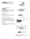
Be sure to perform grounding.
Attach a ground wire to either the
outdoor unit or indoor unit.
If there is a grounding terminal
inside the room, use the grounding
screw inside the indoor unit.
Be sure to apply the provided labels to both
ends of the inter-unit cables to prevent mis-
wiring. The units will not function if the wiring
connections are incorrect.
A is the indoor unit with
refrigerant tubing that is
connected to service valve
A (bottom) of the outdoor unit.
refrigerant tubing that is
connected to service valve B
(second from the bottom) of
the outdoor unit.
B is the indoor unit with
Indoor unit C
refrigerant tubing that is
connected to service valve
C (third from the bottom)
of the outdoor unit.
C is the indoor unit with
Indoor unit D
refrigerant tubing that is
connected to service valve
D (top) of the outdoor unit.
D is the indoor unit with
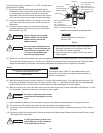
1 2
1 2 3 4 5 6 7 8 9 10 11 12
Power supply
(conduit)
Inter Unit
(conduit)
Inter Unit
(conduit)
# ... AWG (American Wire Gauge)
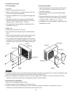
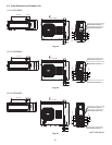
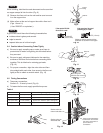
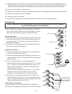
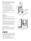
5-5. Wiring Instructions for the Outdoor Unit
Be sure to correctly align inter-unit cables A, B, C and D.
Use a dedicated air conditioner circuit for power.
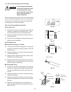
To make connections to the outdoor unit, remove the inspection panel and tubing panel.
Do not bring the inter-unit cables or power cable into contact with tubing or service valves.
Use outdoor unit cable fasteners and fasten the inter-unit cables at the location where the cables are double-
sheathed.
Arrange the wiring so that the inter-unit cables are contained in the inspection panel and tubing panel, as shown in
Fig. 31.
CAUTION
Fig. 31