


Page 6
User’s Manual DRF Series
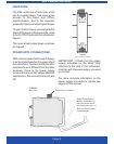
SIGNAL ADJUSTMENT
To proceed to adjust a range of input and
output signals, first select with the
appropriate jumpers, the signal ranges
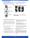
Adjustment Example for model DRF-POT
1.- Connect potentiometer to input
terminals
(8 «term+», 9 «term-» and 7 «signal»)
2.- Connect a multimeter to the output
signal terminals
(4 and 5 for mA or 4 and 6 for
Vdc).
(Values in brackets are examples for a
calibration 0/100% = 0/10Vdc)
3.- Input a zero signal (0 %).
Operate offset potentiometer until
getting a zero output
(0Vdc).
4.- Input the difference between the high
and low input levels (100-0=100% Aac).
Operate span potentiometer until
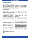
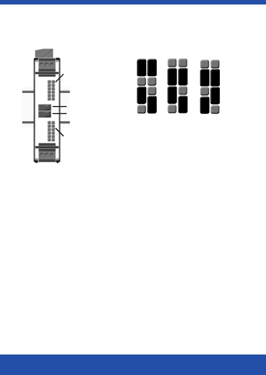
FIGURE 3
F
RONT VIEW
WITHOUT
COVER
SELECTION JUMPERS
OUTPUT S IGNAL
SPAN POTENTIOMETER
OFFSET P OTENTIOMETER
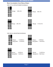
Selection Jumpers : Input Signal Range
(See next page)
SELECTION JUMPERS
INPUT SIGNAL
getting an output which is the
difference between the high and low
output levels
(10-0=10Vdc).
5.- Input low input level
(0 %).
Operate offset potentiometer until
getting the low level output
(0Vdc).
6.- Input high input level and check that
that the output also matches the
desired level
(100 % =10Vdc).
If more accurate measurement is needed,
repeat steps 5 and 6.
Most of the input / output combinations
will be properly adjusted within the
instrument accuracy after these steps.
Close front cover once calibration is
finished.
which include your desired adjustment.
Then proceed to the adjustment.
Selection Jumpers : Output Signal Range
0/20mA
(4/20mA)
0/10Vdc 0/1Vdc