


Page 5
User’s Manual DRF Series
QUICK GUIDE
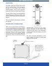
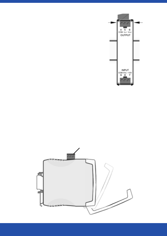
The DRF units have a front cover which
can be opened down. This cover gives
access to the Span and Offset
potentiometers, and to the selection
jumpers for input and output signal ranges.
To open the front cover, press slightly the
sides of the cover at the upper side, close
to the OUTPUT terminals, as indicated on
Figure1.
The cover is free to open down, as shown
on Figure2.
POWER SUPPLY CONNECTIONS
DRF units are powered through the plug-
in terminal positioned on the upper side of
the instrument. This terminal is placed in
a transverse axis, different from the other
terminals. Close to the power supply
terminal there is a small yellow label with
indications on the connections for AC and
DC
FIGURE1
F
RONT VIEW WITH COVER
FIGURE 2
S
IDE VIEW
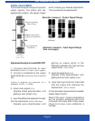
FRONT COVER OPENING:
A
CCESS TO JUMPERS FOR
INPUT
AND OUTPUT RANGE
SELECTION
, AND ACCESS TO
SPAN AND OFFSET ADJUST
POTENTIOMETERS
POWER S UPPLY TERMINAL
IMPORTANT !! Check that the power
supply indicated on the white label
attached to the side of the instrument,
matches with the power supply you want
to connect.
For more accurate information on the
power supply connections, please see
page 6 of this manual.