


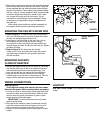
2. When using a standard outlet box install a header between
joists and securely mount outlet box to header. Using two
screws supplied with the outlet box attach socket hanger
securely to outlet box. Place rubber pads between hanger
and box. Using 3" screws (supplied) install screws through
the socket hanger mounting slots, outside of the outlet
box, through the ceiling and into the header. Do not
overtighten or socket hanger may be damaged. These
screws serve as supplemental support independent of
the outlet box.
When using a listed outlet box marked acceptable for
fan support, follow instructions provided with the box.
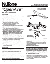
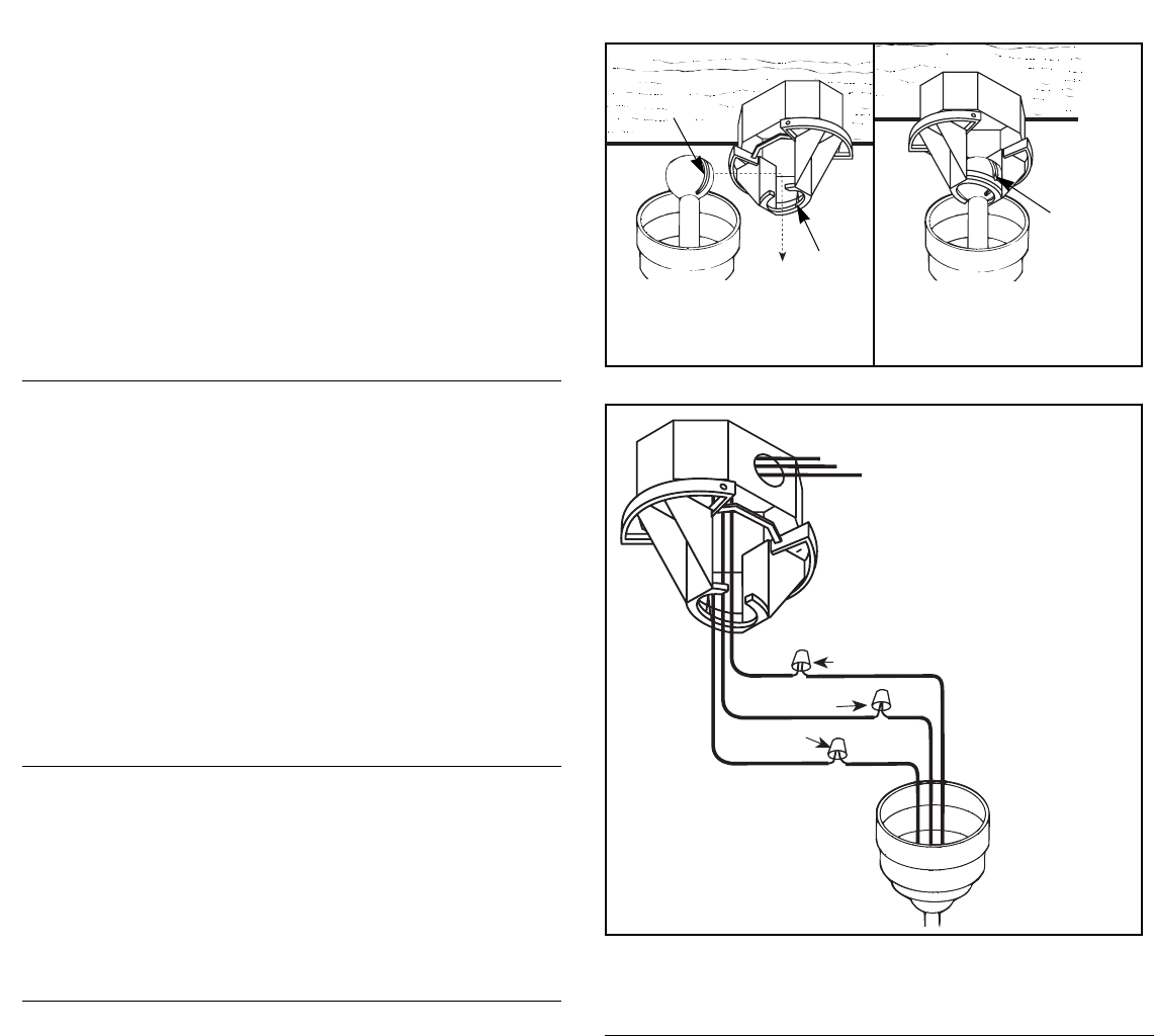
MOUNTING THE FAN WITH DOWN ROD
1. Refer to Figure 6. To install the ball and stem assembly
to the fan, feed the wires from the fan through the rubber
canopy, the ceiling canopy and down rod.
2. Insert stem of rod into flange on the top of fan. (It may
be necessary to back out the set screw in flange).
Line up holes in stem and flange and insert smooth pin
through flange and stem. Secure pin with hitch pin. Tighten
set screw in flange.
3. Refer to Figure 6. Run wires from fan through
rubber cover. Lift fan and place ball hanger into socket
of socket hanger. Rotate fan until groove in ball locks
with tab in socket.
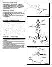
MOUNTING FAN WITH
CLOSE UP ADAPTER
1. Remove soft plastic bushing from the center of the ceiling
cup. Secure ceiling cup to top of fan using three screws
and lockwashers provided in the hardware bag. ( The
down rod and ball are not required for this installation.)
2. Hang the fan from the tab on the back of the hanger
bracket using one of the holes in the ceiling cup. This will
support the fan while wiring connections are made.
WIRING CONNECTIONS
Refer to Figure 4.
All wiring must comply with national and local codes.
Be certain the power is disconnected before proceeding.
1. Connect fan wires to house supply wires using listed wire
connectors. Make connections as follows: Black to black,
white to white and green ground wire to green or bare
copper ground from house supply.
IMPORTANT: For wall switch control use only listed
general use switches.
2. After splices are made turn them upwards and carefully
push into outlet box with white and green wires on one
side of outlet box and black wires on the other side.
3. Using four screws (supplied) secure ceiling cup to socket
hanger.
G
W
BLACK (FAN)
WHITE
(COMMON)
GREEN
(GROUND)
BK
FIGURE 3
FIGURE 4
HOUSE SUPPLY
WIRES
GROOVE
TAB
TAB
LOCKS IN
GROOVE
LIGHT KIT
USE ONLY PFLK-123WH. Do not attempt to use any other
model.