


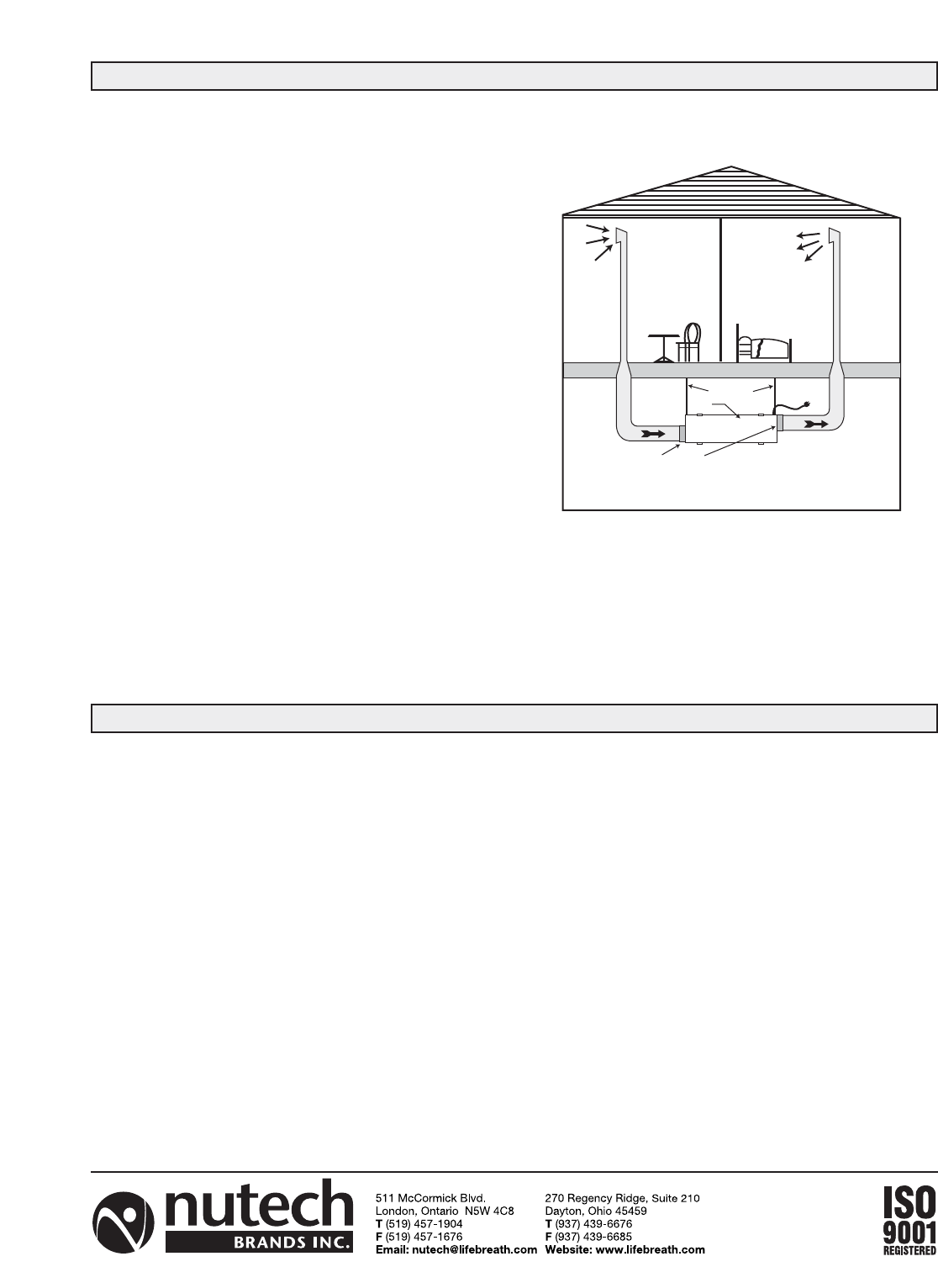
TFP Independent Installation
No HRV, Radiant Heating System
LOCATION
1. A TFP is usually installed in a basement area
where air flow noise will be negligible to the occu-
pants.
2. A central location between the clean air supply
grille and return grille is recommended.
MOUNTING
Refer to “Mounting” under Type 2 Installations.
DUCTING
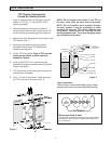
1. Install (2) 6” oval port collars (provided) on TFP
cabinet with (8)8/32” X 3/8” sheet metal screws
provided (Fig.4).
2. Ducting will usually consist of one return with grille
from one side of the home, and one supply
with
grille at the opposite end of the home (Fig. 4).
3. Ductwork should be no smaller than the size of the
port collars (6”) on the TFP.
4. Ductwork should be kept as short and straight as
possible to allow for good air circulation.
NOTE: For installations of more than one return or
supply (greater than .5 e.s.p.) , it is often necessary to
add an inline fan to the system as a booster.
OPERATING INSTRUCTIONS
A lighted ON/OFF switch indicates that the unit is
operating. It is recommended the unit run continuously
to provide the full benefits of particulate removal from
your home.
ANNUAL CHECK-UP
As each home has differences of size, occupancy,
loca-
tion, infiltration rates and homeowner needs, it is hard
to
estimate when the collectors will need to be changed.
Because of the way air moves through the TFP, the
collectors are divided into 3 separate sections.
Collectors 1 & 2, then 3 & 4 and then 5 & 6. Collectors
1 & 2 will need to be replaced before the others, then
3 & 4 and so on. You may want to change 1 & 2 again
before 3 & 4 or 5 & 6.
The collectors will slide out. Some discolouration of
the collector medium can be expected and when loose
dust falls from the collector, it is time to replace it.
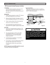
Turn the TFP, furnace fan and HRV off. Open the door
and slide out the collectors to check buildup and do an
annual inspection of overall unit. Before replacing any
collectors, vacuum any dust inside the cabinet or sur-
rounding area. When replacing the collectors, make
sure the pleats are horizontal when sliding collec-
tors back into the TFP. Close the door and restart
TFP, furnace and HRV fan.
When your TFP is installed with a forced air heating
system you are still required to use the recommended
furnace filter. This may be a good time to inspect this
filter as well.
When new collectors are required, call your Lifebreath
dealer.
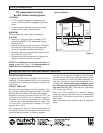
TYPE 3 INSTALLATION
OPERATING INSTRUCTIONS AND ANNUAL CHECK-UP
FLOOR JOIST (Header)
Return Grille
High wall
or floor grille
optional
6" port collars
Access door
Hanging
straps (2)
Ducting
not included
BASEMENT
High wall
or floor
grille
optional
1st or 2nd
STORY
Clean air supply
TFP
Type 3 Installation
Figure 4