


3
TFP Connected to Heat Recovery Ventilator
LOCATION
The TFP should be located in the main trunk of
the fresh air to house line, after the Heat
Recovery
Ventilator (HRV) and before any branch
lines. (Fig. 3)
MOUNTING
1. Locate mounting bolts (4) on side of TFP cabinet
for vertical hanging (Fig. 3) and remove.
2. Measure distance between the bolts and mark it
on the floor/header joist where the TFP is to be hung.
3. Fasten hanging straps to floor joists using wide
head nails or screws with washers.
4. Insert hanging bolts through prepunched holes in
straps and lift TFP into position. Tighten and secure bolts.
DUCTING
1. Install (2) 6” oval port collars (provided) on TFP
cabinet with (8) 8/32” X 3/8” sheet metal screws
provided (Fig. 3).
2. The ducting between the TFP and the HRV,
and between the TFP and the main supply
trunk line to the house, should be kept as
straight as possible.
3. A relief opening or breathing T is required to
prevent pressure differences.
4. A short piece (1-2 foot) of flexible ducting should
be used on both sides of the TFP (Fig. 3).
This will reduce vibration and noise transfer
if present.
NOTE: Please refer to the HRV installation manual
for proper ducting of that appliance.
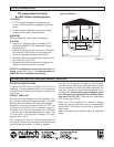
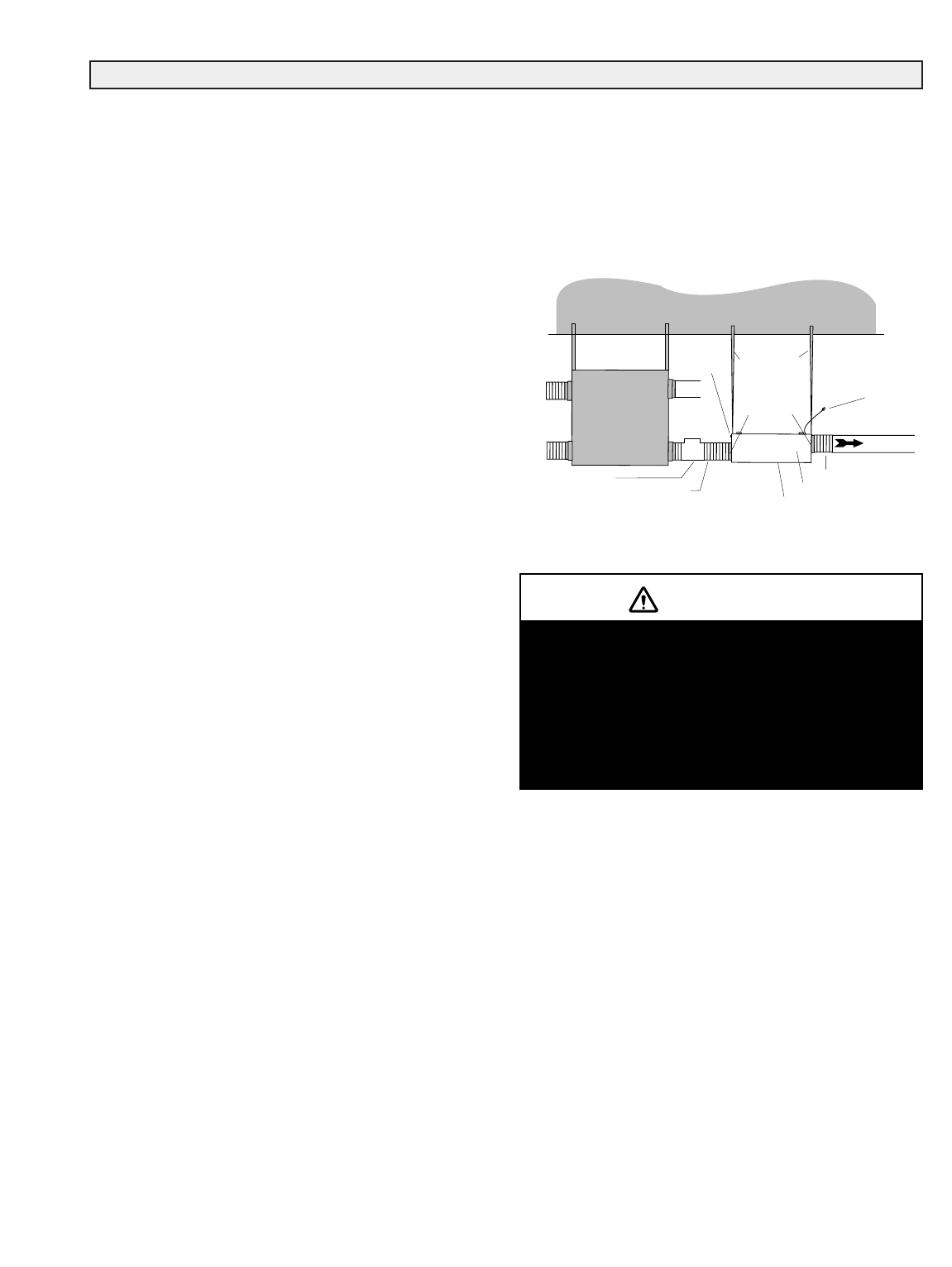
Type 2 Installation
* “Breathing T” is designed to assist in neutralizing
pressure differences which can occur between HRV
and TFP when joined together.
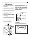
TYPE 2 INSTALLATION
TFP
Hanging straps (4)
Relief opening
(breathing T)
or leave a
4
" -
6
"
gap between the
TFP and the HRV
6
"
port collars
Access door
Power cord
Flexible ducting
(fresh air supply)
Air flow
HRV
T
o
B
R
A
N
C
H
L
IN
E
S
Mounting bolts
Main supply trunk
Flexible ducting
TFP air cleaner
FLOOR JOISTS
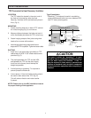
The room in which the “breathing T” is open
should be free of combustion equipment such as
gas hot water tanks and furnaces. If the “T”
must be exposed in these areas, a pressure test
(spillage or backdraft test) should be conducted
on the combustion equipment after everything is
installed.
CAUTION
Figure 3