


It is necessary to have balanced air flows in an HRV. The volume of
air brought in from the outside must equal the volume of air exhaust-
ed by the unit. If the air flows are not properly balanced, then;
• The HRV may not operate at its maximum efficiency
• A negative or positive air pressure may occur in the house
• The unit may not defrost properly
• Failure to balance HRV properly may void warranty
Excessive
positive
pressure
may drive moist indoor air into the
external walls of the building where it may condense (in cold weather)
and degrade structural components. May also cause key holes to
freeze up.
Excessive
negative pressure may have several undesirable effects.
In some geographic locations, soil gases such as methane and radon
gas may be drawn into the home through basement/ground contact
areas. Excessive negative pressure may also cause the backdrafting
of vented combustion equipment.
Read the Application Warning on the front of this manual!
Prior to balancing, ensure that:
1. All sealing of the ductwork system has been completed.
2. All of the HRV's components are in place and functioning properly.
3. Balancing dampers are fully open.
4. Unit is on HIGH speed.
5. Air flows in branch lines to specific areas of the house should be
adjusted first prior to balancing the unit. A smoke pencil used at
thegrilles is a good indicator of each branch line's relative air flow.
6. After taking readings of both the stale air to the HRV duct and
fresh air to the house duct, the duct with the lower CFM ([L/s]
velocity) reading should be left alone, while the duct with the higher
reading should be dampered back to match the lower reading.
7. Return unit to appropriate fan speed for normal operation
Balancing Procedure
The following is a method of field balancing an HRV using a Pitot
tube, advantageous in situations when flow stations are not installed
in the ductwork. Procedure should be performed with the HRV on high
speed.
The first step is to operate all mechanical systems on high speed,
which have an influence on the ventilation system, i.e. the HRV itself
and the forced air furnace or air handler if applicable. This will provide
the maximum pressure that the HRV will need to overcome, and allow
for a more accurate balance of the unit.
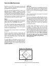
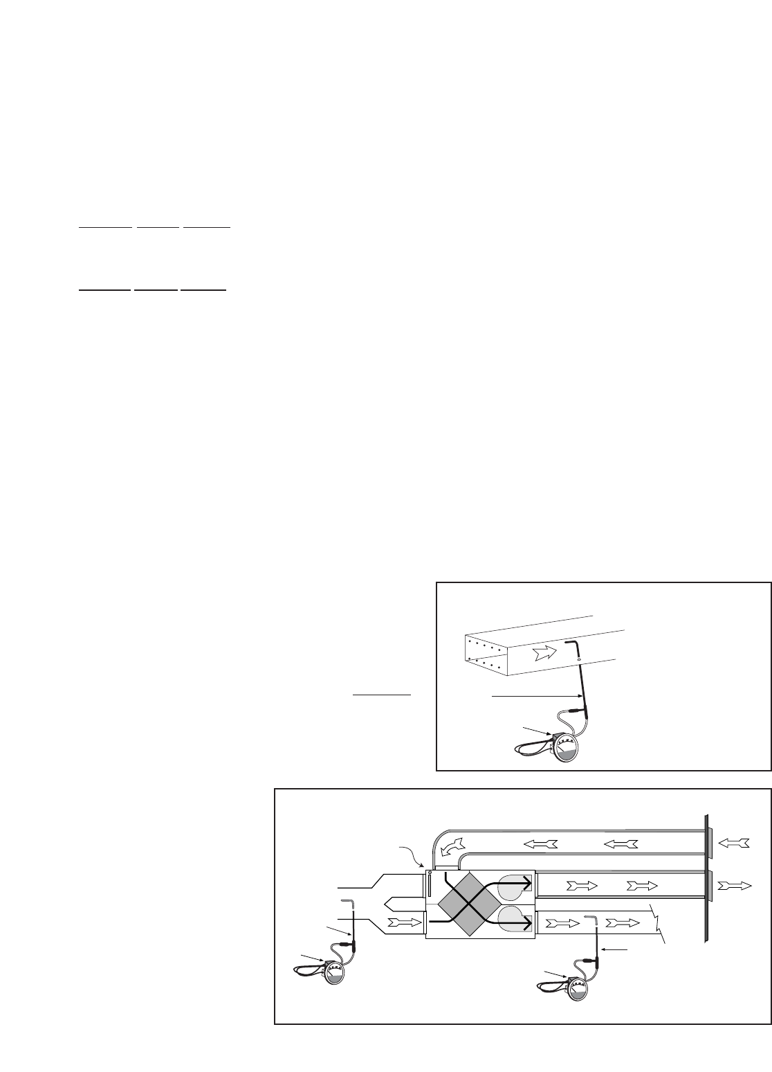
Drill a small hole in the duct (about 3/16"), three feet downstream of
any elbows or bends, and one foot
upstream of any elbows or bends.
These are recommended distances
but the actual installation may limit the
amount of straight duct.
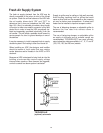
The Pitot tube should be connected to
a magnehelic gauge or other
manometer capable of reading from 0
to 0.25 in. (0-62 Pa) of water, prefer-
ably to 3 digits of resolution. The tube
coming out of the top of the pitot is
connected to the high pressure side of
the gauge. The tube coming out of the
side of the pitot is connected to the
low pressure or reference side of the
gauge.
Insert the Pitot tube into the duct; pointing the tip into the airflow.
For general balancing it is sufficient to move the pitot tube around in
the duct and take an average or typical reading. Repeat this proce-
dure in the other (supply or return) duct. Determine which duct has the
highest airflow (highest reading on the gauge). Then damper that air-
flow back to match the lower reading from the other duct. The flows
should now be balanced. Actual airflow can be determined from the
gauge reading. The value read on the gauge is called the velocity
pressure. The Pitot tube comes with a chart that will give the air flow
velocity based on the velocity pressure indicated by the gauge. This
velocity will be in either feet per minute or metres per second. To
determine the actual airflow, the velocity is multiplied by the cross
sectional area of the duct being measured.
This is an example for determining the airflow in a 6" duct.
The Pitot tube reading was 0.025 inches of water.
From the chart, this is 640 feet per minute.
The 6" duct has a cross sectional area of =
[3.14 x (6"÷12)2]÷4
= 0.2 square feet
The airflow is then:
640 ft./min. X 0.2 square feet = 128 cfm
For your convenience, the cross sectional area of some common
round duct is listed below:
DUCT DIAM. (inches) CROSS SECTION AREA (sq. ft.)
5 0.14
6 0.20
7 0.27
The accuracy of the air flow reading will be affected by how close to
any elbows or bends the readings are taken. Accuracy can be
increased by taking an average of multiple readings as outlined in the
literature supplied with the Pitot tube.
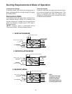
MAGNEHELIC
DUCT
AIR FLOW
Pitot tube
Magnehelic gauge
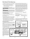
Pitot tube and gauge
Pitot Tube Air Flow Balancing
Pitot Tube Air Flow
Balancing Kit
c/w magnehelic gauge,
Pitot tube, hose and
carry case.
PART NO. 99-167
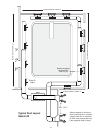
Place pitot tube a minimum of 18" from blower or elbows
Note: Duct connections may vary,
depending on model.
Outdoors
M
A
G
N
E
H
E
L
IC
Magnehelic
gauge
Pitot
tube
M
A
G
N
E
H
E
L
IC
Magnehelic
gauge
Pitot
tube
HRV must be in ventilate
mode when balancing
proceedure is performed
20