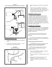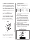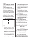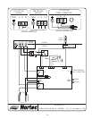
current) across terminals 1 and 2 on the low voltage
control terminal.
Caution: This is the “common” wire from the
transformer that is connected to the ground. It will
short on/off control loop if it touches a grounded
metal surface.
A - Wall or Duct Mounted Control On/Off
Humidistat: Wired to close when there is a drop in
humidity and open when the setpoint is reached. Set
to desired % RH.
B - Duct Mounted Safety High Limit On/Off
Humidistat (if used): Wired to close when there is a
drop in humidity and open when the safety setpoint is
reached. Set to approximately 85% RH as a safety to
help prevent saturation and wetting in the duct (not
required when using blower pack kit).
C - Duct Mounted Safety Air-Proving On/Off
Switch (if used): Wired to close when sensing air flow
and open when no air flow is sensed. Used as a
safety to prevent saturation of the duct when there is
no air flow (not required when using blower pack kit).
1. NORTEC offers various versions of A, B and C
to suit each application. In general, A is
essential for in space applications, C is essential
for induct applications, whereas B is highly
recommended in ducted applications.
2. Field wiring from the humidistat to the humidifier
and between devices should be a minimum of 18
AWG and kept as short as possible.
3. Low voltage control terminal strips are provided
in the electrical compartment. Internal sides are
factory wired. External sides are for field wiring.
(See Figure #14).
4. Each humidifier is supplied with a wiring diagram
inside.
Control Installation
1. Wall Humidistat: Mount any wall humidistat
(control or high limit) over the standard electrical
box at a height similar to a typical thermostat.
Any wall humidistat should be in a location
representative of overall space being humidified
and not in the path of the blower pack or air
supply grille. Do not mount on an outside wall
where temperature fluctuation can affect the
control response.
2. Duct Humidistat: Mount the duct humidistat In a
location representative of overall air humidity,
(usually the return duct). Do not mount it directly
in front of the steam distributor or in a turbulent
or mixing zone. Mount it where the air’s humidity
and temperature are uniform and representative
of spaces being humidified.
3. High Limit Duct Stat: Mount the duct high limit
humidistat downstream of the steam distributors
far enough that, under normal humidity and air
flow conditions, steam will have been fully
absorbed (typically at least 10 feet). It must be
located to sense high humidity only when
uniform and representative air is over-humidified
or approaching saturation.
4. Duct Air Proving Switch: Mount the duct
air-proving switch so that it is able to sense air
flow or lack of it. Wire it to close when air flow is
sensed and open when air flow fails.
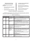
5. Check operation of all on/off controls before
starting the humidifier.
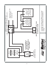
Note: For wiring interface with a fan, see wiring
diagram provided on page 13. Steam humidifier will
turn on fan when increase in humidity is required.
OPERATION
INTRODUCTION
The NORTEC RESDELUX humidifier is designed
to provide clean steam humidification at an economical
price. It utilizes NORTEC’s patented electronic
Auto-Adaptive internal control system for high
efficiency and low waste of water and electricity.
RESDELUX OPERATION
When the humidifier is first turned on, the
controller starts with a self test procedure, which takes
about 10 seconds. The test consists of activating for a
short time the drain valve, fill valve, and power relays.
The sound of the working solenoids is an indication of
-7-
A
B
C
1
2
External
Internal
Figure #14
External Wiring Of On/Off Controls


