


5
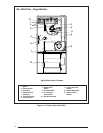
90+ AFUE Two - Stage Models
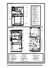
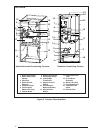
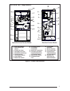
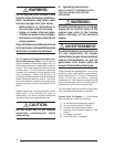
Figure 3. Furnace Parts Identified
Upflow/Horizontal Furnace Models
20
5
7
3
8
18
9
17
12
16
14
10
17
5
3
12
10
14
9
8
11
20
19
7
16
18
1 Ignitor (Not Shown)
2 Flame Sensor (Not
Shown)
3 Primary Gas Valve
4 Secondary Gas Valve
5 Flame Roll-out Switch(s)
6 Pressure Switch
7 Vent Pressure Switch
8 Control Board
9 Blower Door Switch
Downflow Furnace Models
10 Vent Safety Switch
11 Low Voltage
Transformer
12 Supply Air Limit Switch
13 Circulating Air Blower
Assembly (Not Shown
on Downflow Model)
14 Induced Draft Blower
15 Condensate Drain
Tube
16 In-Line Drain
Assembly
17 Burner View Port
18 Front Header Box
19 Combustion Air
Intake (Not Shown
on Upflow Model))
20 Exhaust Vent
(Not Shown on
Downflow Model)
4
6
6
11
13
15
4
15