


3
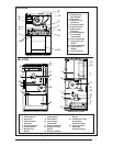
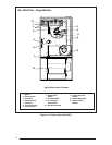
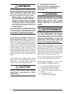
1 Ignitor
2 Flame Sensor
(Not Shown)
3 Gas Valve
4 Flame Roll-out
Switch(s)
5 Pressure Switch
6 Control Board
7 Blower Door
Switch(s)
8 Exhaust Adapter
9 Low Voltage
Transformer
10 Burner Assembly
11 Supply Air Limit
Switch
12 Blower Assembly
13 Induced Draft
Blower
14 Vent Transition
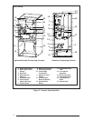
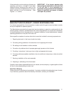
1 Ignitor
2 Flame Sensor
3 Gas Valve
4 Flame Roll-out
Switch(s)
5 Pressure Switch
6 Control Board
7 Blower Door
Switch
80+ AFUE
2
5
7
6
3
10
4
1
11
8
12
14
13
9
8 Vent Assembly
(Upflow Only)
9 Vent Switch
10 Low Voltage
Transformer
11 Burner Assembly
12 Supply Air Limit
Switch
13 Blower Assembly
14 Induced Draft
Blower
15 Combustion Tube
w/insulation
(Downflow Only)
16 Vent Transition
Assembly
(Downflow Only)
Upflow/Horizontal Furnace
Upflow/Horizontal Furnace
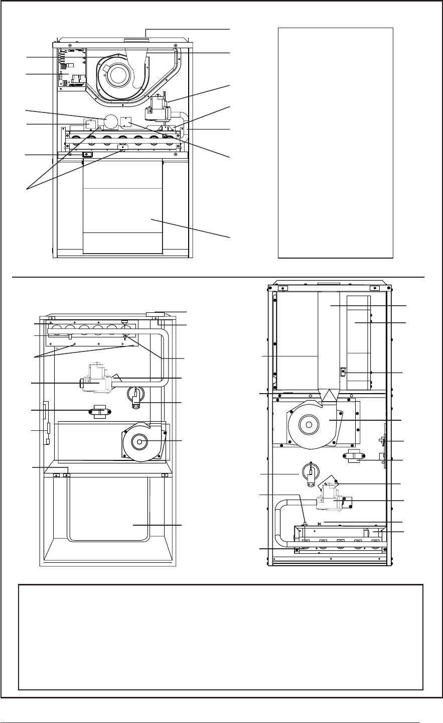
5
2
9
3
4
1
6
7
13
15
10
12
14
16
11
Downflow Furnace
Figure 1. Furnace Parts Identified
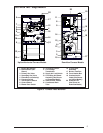
13
6
5
9
7
4
12
11
10
1
3
14
8
80+ AFUE