


5
AIR HANDLER INSTALLATION
Packaging Removal
Remove the shipping crate and User’s Manual from the
equipment. Take care not to damage the tubing connections
when removing the crate.
Minimum Clearance Requirements
This air handler must be installed with ample clearance
for easy access to the air fi lters, blower assembly, and,
controls. Allow 24 inches minimum clearance from the
front of the motor and refrigerant access panels for
service and maintenance. However 36 inches is strongly
recommended.
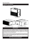
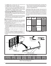
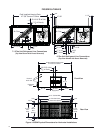
Horizontal Mounting Applications
B5SM air handlers can be suspended from support rods
at each corner and are supplied with the required 1/2-13
NC hardware. The installer only needs to supply the ½”
full threaded support rods in an appropriate length for
their application. NOTE: These units can be supported
with 3/8” full threaded support rods, however all mounting
hardware must be fi eld supplied. Once in position, verify
the unit is level. See Figure 4 (page 10).
CAUTION:
When raising the air-handler for horizontal
mounting, always use safe lifting methods
and equipment. Always support the unit along
its entire width. Failure to do so may result in
damage to the lower panels or other equipment.
If determined safe for your application the
shipping pallet may be utilized with a forklift
for this operation.
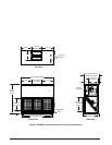
Vertical Mounting Applications
Verify the unit is level and there is adequate clearances to
service the unit and provide the minimum 2” trap needed
for the condensate drain. See Figure 5 (page 11).
Condensate Drain
B5SM air handlers have condensate drain ports on both
sides of the unit, and may be confi gured for drainage from
the left, right or both sides (Figures 4 or 5). Connection to
the drains can be made with a ¾” threaded PVC adapter.
Units are confi gured at the factory with the service side
drain open and a threaded PVC drain plug installed on
the opposite side. Each drain line installed requires its
own drain trap. To ensure proper drainage, the installed
drain trap(s) must provide a minimum trap of 2 inches.
Note: It is recommended that a secondary drain pan be
used when the unit is hung above an enclosed ceiling.
Connecting Refrigerant Tubing
WARNING:
Evaporator Coils are factory shipped with a
nitrogen charge. Avoid direct face exposure or
contact with valve when gas is escaping. Always
ensure adequate ventilation is present during
the depressurization process. Any uncertainties
should be addressed before proceeding.
• When connecting refrigerant linesets together, it is
recommended that dry nitrogen be fl owing through the
joints during brazing. This will prevent internal oxidation
and scaling from occurring.
• Refrigerant tubing should be routed in a manner that
minimizes the length of tubing and the number of bends
in the tubing.
• Refrigerant tubing should be supported in a manner
that the tubing will not vibrate or abrade during system
operation.
• Tubing should be kept clean of foreign debris during
installation.
• Every effort should be made by the installer to ensure
that the fi eld installed refrigerant containing components
of the system have been installed in accordance with
these instructions and sound installation practices to
insure reliable system operation and longevity.
• Always refer to the installation instructions supplied with
the outdoor unit for piping requirements. The suction
and liquid lines must be sized in accordance with the
condensing unit specifi cations.
• If precise forming of refrigerant lines is required, a copper
tubing bender is recommended. Avoid sharp bends and
contact of the refrigerant lines with metal surfaces.
• A fi lter dryer is provided with the unit and must be
installed in the liquid line of the system. If the installation
replaces a system with a fi lter dryer already present
in the liquid line, the fi lter dryer must be replaced with
the one supplied with the unit. The fi lter dryer must be
installed in strict accordance with the manufacturer’s
installation instructions.
• B5SM air handlers are supplied with a direct expansion
refrigerant coil and thermostatic expansion valves.
Refrigerant line connections are located on the motor
side (service side) of cabinet and require sweat
connections.
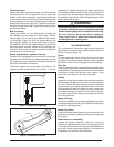
NITROGEN
HEALTH
FLAMMABILITY
REACTIVITY
0 Minimal Hazard
1 Slight Hazard
1
0
0