


14
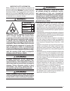
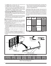
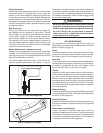
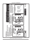
Figure 7. Typical Air conditioner Thermostat Connections
BLOWER
MOTOR
GND
TO FIELD
SUPPLIED DISCONNECT
SINGLE STAGE
HEAT/COOL THERMOSTAT
OUTDOOR
SECTION
FREEZESTAT
SINGLE STAGE HEAT/COOL THERMOSTAT- NO ECONOMIZER
AIR HANDLER
SECTION
TERMINAL
BOARD
G
C
W2
W1
O
Y
R
C
Y
R
RCG
YW
L1
L2
L3
NOTE:
C &W2 to be connected to electric heat.
See Note
BLACK
BLACK
BROWN
GREEN
OPTIONAL
BLOWER
MOTER
GND
TO FIELD
SUPPLIED DISCONNECT
SINGLE STAGE
HEAT/COOL
THERMOSTAT
OUTDOOR
SECTION
FREEZESTAT
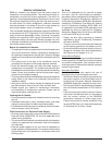
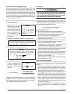
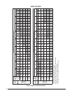
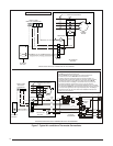
SINGLE STAGE HEAT/COOL THERMOSTAT- WITH ECONOMIZER
AIR HANDLER
SECTION
TERMINAL
BOARD
G
C
W2
W1
O
Y
R
C
Y
R
RCG
YW
L1
L2
L3
s
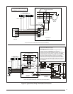
C7400A
B
Y1
OPTIONAL
ECONOMIZER
W7459A
C7150
M.A.S.
TB-11 M7415A
T
T1
MA
MIN.
POT.
P1
P
TR1
TR
Y2
S
TR 1
TR
o
S
1
3
2
4
T
P
T1
2K
JUMPER
WIRE
5
P1
r
1S
1S
AB
7
9
46
13
BLU-14”
YEL-18”
GRY-90”
GRN
GRY
YEL
BLK
ORN
RED
RED
WHITE
BLUE
VIO-14”
GRN-18”
GRN-18”
RED-12”
GRY-12”
BLK-12”
BLU-12”
BLK-12”
NOTES:
1. C & W2 to be connected to electric heat.
2. Remove BLACK wire from air handler low voltage terminal board
Y terminal and connect to YELLOW wire from economizer.
3. 2nd Stage refrigerant cooling with optional economizer installed. A 2
stage thermostat is required for simultaneous operation of the economizer
and refrigerant system. Connect Y2 from 2 stage thermostat to BLUE
wire from economizer. If installing an economizer in this unit, refer to the
Economizer installation instructions for proper set up and operation.
4. Heat Pump Economizer Relay. For heat pump applications only, connect B
from thermostat to GREY wire from Economizer. Required for proper operation
of an economizer (optional) in the heat pump Heating mode. If installing an
economizer in this unit, refer to the Economizer installation instructions for
proper set up and operation.
Note 4
Note 2
Note 1
Note 3
BLACK
BLACK
GREEN
OPTIONAL