


6
41840-A McAlby Court, Murrieta, CA 92562
(800) 451-9343, email: sales@nimbuswater.com
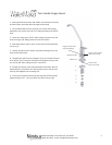
Feed and Drain Connecon
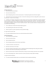
Feed Connecon
1. Locate and turn o the angle stop valve on the cold water line feeding the sink. This
valve will usually be located under the sink on the pipe coming out of the wall.
2. When the angle stop valve is closed, relieve pressure in the line by opening the cold
water tap on the sink.
3. Disconnect the cold water faucet feed line at the angle stop valve.
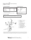
4. Install the feed adapter into the angle stop. (Fig. 1)
5. Firmly press the green 1/4” tubing into the 1/4" connector on the feed adapter.
6. Connect the cold water faucet feed line into the feed adapter.
7. Aach the small feed valve warning tag from the parts bag to the feed valve.
8. Aach the Shuto Warning label to the system so that it is directly visible. Fill out the
Date of Installaon label and aach to the side of the system.
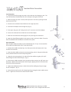
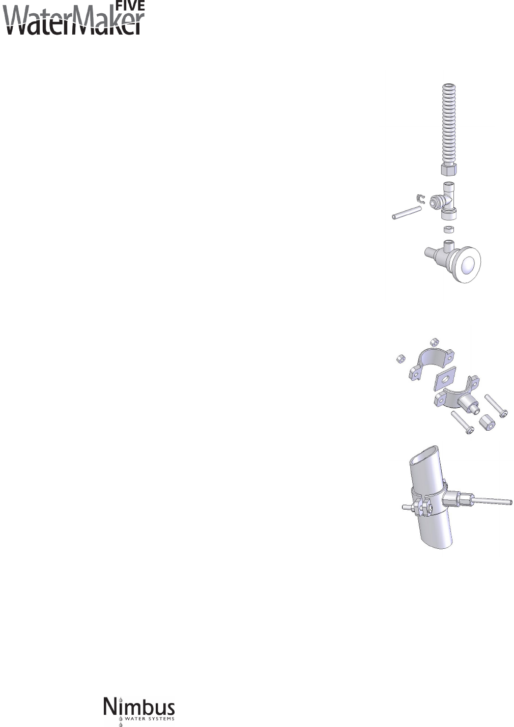
Drain Connecon
Note: The drain saddle assembly must be installed before the 'P' trap. Do not install the
drain saddle assembly between the 'P' trap and the wall.
1. Posion drain saddle assembly (Fig. 2) on drain pipe under sink between the P trap
and the sink connecon.
2. Orient the drain saddle so that the connec tor opening points in the general direcon
of the planned loca on for the R.O. dispensing faucet.
3. Using the connector opening in the side of the drain saddle as a guide, drill a 3/8"
hole through the wall of the drain pipe. (Fig. 3)
4. Remove drain saddle assembly. Place the adhesive foam pad over the 3/8" hole in the
drain pipe. Replace the assembly onto the drain pipe, aligning the hole in the drain with
the hole in the drain assembly.
5. Tighten the saddle bolts evenly on both sides unl the saddle grips the pipe snugly -
do not overghten. (Fig. 3)
6. Insert the drain tube from the R.O. dispensing faucet through the drain saddle connec-
tor nut. Tighten the connector nut onto the drain saddle.
Fig. 2
Fig. 3
Fig. 1