


NTI KEEMUX Series PS/2 KVM Switch
24
NOTE: Before proceeding, it is important to discharge any static charge you may be carrying by touching any large
metal object (away from the KEEMUX).
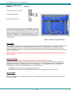
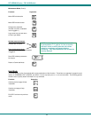
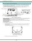
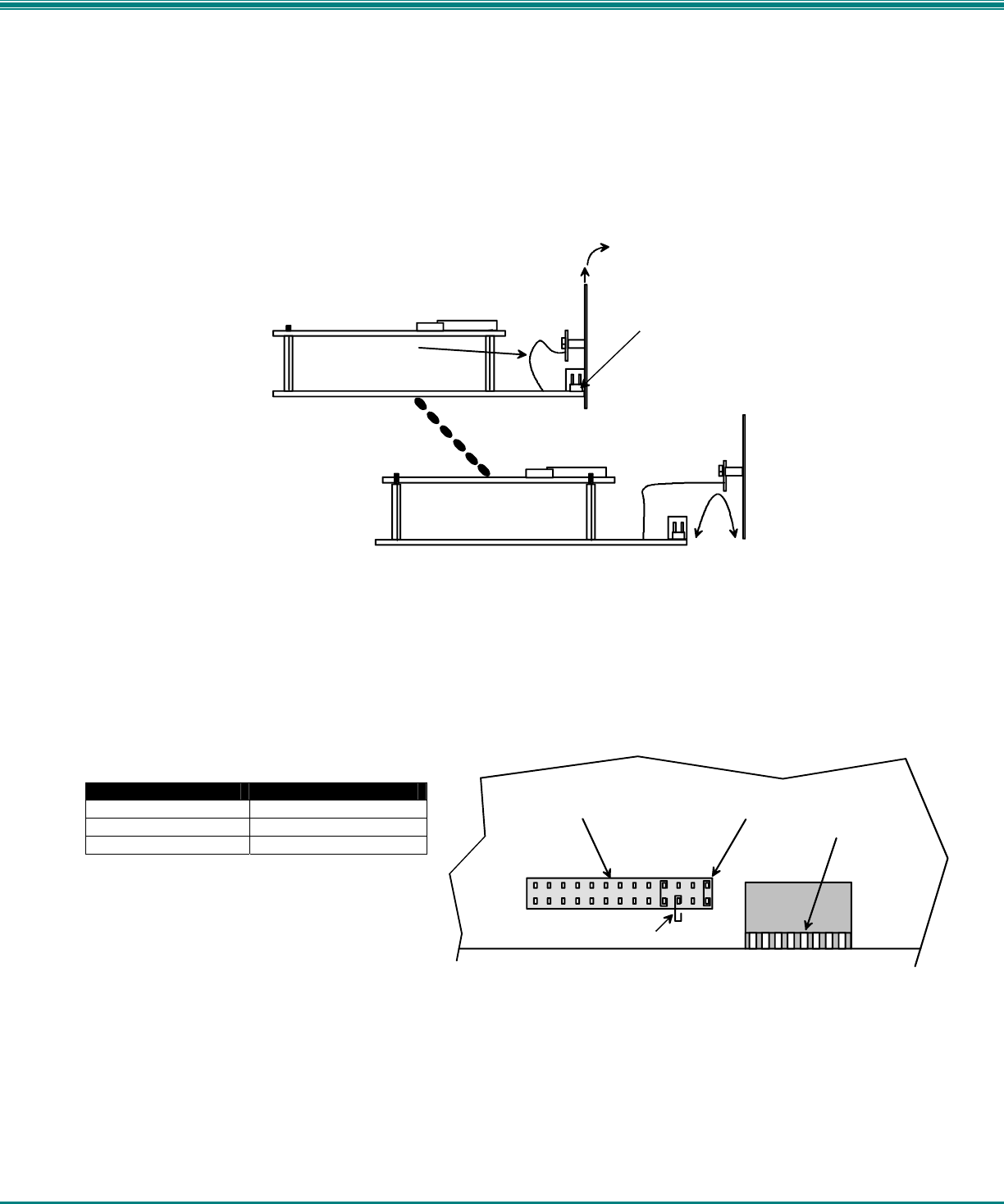
4. With it loosened, grasp firmly the front panel and slide the front panel up out of the slots in the plastic case that support it.
Once clear of the case, pivot the assembly forward approximately 1", just enough to provide access to the jumper block. (See
Fig. 19.) Be careful not to dislodge the connection of the ribbon connecting the front panel to the digital board. If it appears
to become loose, be sure to reseat the connection before re-assembly. Now follow the instructions under "CONFIGURING
THE JUMPER BLOCK" on page 24.
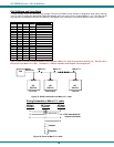
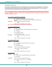
Figure 19- Clear the jumper block for configuration access
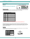
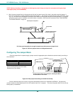
Configuring The Jumper Block
Once the jumper block is exposed, apply a jumper across the appropriate pins to disable the desired mode(s) according to
the chart below.
Pin Designation Mode
KCMD Command Mode*
BRDC Broadcast Mode
SCAN Scan Mode
*Note: Putting a jumper across pins KCMD to
disable Command Mode will also disable
Broadcast and Scan Modes.
Figure 20- Place jumpers according to desired functionality
Once the desired jumpers are in place, reverse the disassembly process to re-assemble the KEEMUX. Be particularly
careful to make sure all dip switches are in the OFF position (see Fig. 1 on page 3). Do not turn the power ON until the unit has
been properly re-assembled.
L
C
D
E
K
C
M
D
B
R
D
C
S
C
A
N
JUMPER BLOCK
DIP SWITCHES
Drawing shows jumper across SCAN pins, disabling Scan Mode.
Broadcast Mode is still enabled.
JUMPER (unused)
If the unit has an LCD
this jumper will be here.
Lift and pivot front panel......
....and pull forward enough
to access jumper block.
Pull front panel assembly far enough forwared to provide access to jumper block.
Jumper block
Ribbon from LED
board to digital board