


Application Note (Continued)
must be added, one for case to heat-sink (θ
CH
) and one for
heatsink to ambient (θ
HA
). The junction temperature can be
predicted as follows:
T
J
=T
A
+P
D
(θ
JC
+ θ
CH
+ θ
HA
)=T
A
+P
D
θ
JA
T
J
is junction temperature, T
A
is ambient temperature, and
P
D
is the power consumption of the device. Device power
consumption is calculated as follows:
I
IN
=I
L
+I
G
P
D
=(V
IN
−V
OUT
)I
L
+V
IN
I
G
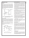
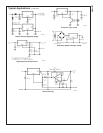
Figure 6 shows the voltages and currents which are present
in the circuit.
Once the devices power is determined, the maximum allow-
able (θ
JA(max)
) is calculated as:
θ
JA(max)
=T
R(max)
/P
D
=T
J(max
−T
A(max)
)/P
D
The LM1085 has different temperature specifications for two
different sections of the IC: the control section and the output
section. The Electrical Characteristics table shows the junc-
tion to case thermal resistances for each of these sections,
while the maximum junction temperatures (T
J(max)
) for each
section is listed in the Absolute Maximum section of the
datasheet. T
J(max)
is 125˚C for the control section, while
T
J(max)
is 150˚C for the output section.
θ
JA(max)
should be calculated separately for each section as
follows:
θ
JA
(max, CONTROL SECTION) = (125˚C - T
A(max)
)/P
D
θ
JA
(max, OUTPUT SECTION) = (150˚C - T
A(max)
)/P
D
The required heat sink is determined by calculating its re-
quired thermal resistance (θ
HA(max)
).
θ
HA(max)
= θ
JA(max)
−(θ
JC
+ θ
CH
)
θ
HA(max)
should also be calculated twice as follows:
θ
HA(max)
= θ
JA
(max, CONTROL SECTION) - (θ
JC
(CON-
TROL SECTION) + θ
CH
)
θ
HA(max)
=θ
JA
(max, OUTPUT SECTION) - (θ
JC
(OUTPUT
SECTION) + θ
CH
)
If thermal compound is used, θ
CH
can be estimated at 0.2
C/W. If the case is soldered to the heat sink, then a θ
CH
can
be estimated as 0 C/W.
After, θ
HA(max)
is calculated for each section, choose the
lower of the two θ
HA(max)
values to determine the appropriate
heat sink.
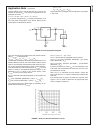
If PC board copper is going to be used as a heat sink, then
Figure 7 can be used to determine the appropriate area
(size) of copper foil required.
10094716
FIGURE 6. Power Dissipation Diagram
10094764
FIGURE 7. Heat sink thermal Resistance vs Area
LM1085
www.national.com9