


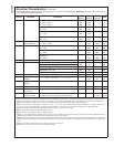


Electrical Characteristics (Continued)
Typicals and limits appearing in normal type apply for T
J
= 25˚C. Limits appearing in Boldface type apply over the entire junc-
tion temperature range for operation.
Symbol Parameter Conditions
Min
(Note 6)
Typ
(Note 5)
Max
(Note 6)
Units
I
LIMIT
Current Limit LM1085-ADJ
V
IN
−V
OUT
=5V
V
IN
−V
OUT
= 25V
3.2
0.2
5.5
0.5
A
A
LM1085-3.3
V
IN
=8V 3.2 5.5 A
LM1085-5.0
V
IN
= 10V 3.2 5.5 A
LM1085-12
V
IN
= 17V 3.2 5.5 A
Minimum Load
Current (Note 10)
LM1085-ADJ
V
IN
−V
OUT
= 25V 5.0 10.0 mA
Quiescent Current LM1085-3.3
V
IN
≤ 18V 5.0 10.0 mA
LM1085-5.0
V
IN
≤ 20V 5.0 10.0 mA
LM1085-12
V
IN
≤ 25V 5.0 10.0 mA
Thermal Regulation T
A
= 25˚C, 30ms Pulse .004 0.02 %/W
Ripple Rejection f
RIPPLE
= 120Hz, C
OUT
= 25µF Tantalum, I
OUT
=3A
60 75 dBLM1085-ADJ, C
ADJ
= 25µF, (V
IN
−V
O
)=3V
LM1085-3.3, V
IN
= 6.3V 60 72 dB
LM1085-5.0, V
IN
=8V 60 68 dB
LM1085-12 V
IN
= 15V 54 60 dB
Adjust Pin Current LM1085 55 120 µA
Adjust Pin Current
Change
10mA ≤ I
OUT
≤ I
FULL LOAD
, 1.5V ≤ V
IN
−V
OUT
≤ 25V
0.2 5 µA
Temperature
Stability
0.5 %
Long Term Stability T
A
=125˚C, 1000Hrs 0.3 1.0 %
RMS Output Noise
(% of V
OUT
)
10Hz ≤ f≤ 10kHz 0.003 %
Thermal Resistance
Junction-to-Case
3-Lead TO-263: Control Section/Output Section
3-Lead TO-220: Control Section/Output Section
0.7/3.0
0.7/3.0
˚C/W
˚C/W
Note 1: Absolute Maximum Ratings indicate limits beyond which damage to the device may occur. Operating Ratings indicate conditions for which the device is
intended to be functional, but specific performance is not guaranteed. For guaranteed specifications and the test conditions, see the Electrical Characteristics.
Note 2: Power dissipation is kept in a safe range by current limiting circuitry. Refer to Overload Recovery in Application Notes.
Note 3: The maximum power dissipation is a function of T
J(max)
, θ
JA
, and T
A
. The maximum allowable power dissipation at any ambient temperature is
P
D
=(T
J(max)
–T
A
)/θ
JA
. All numbers apply for packages soldered directly into a PC board. Refer to Thermal Considerations in the Application Notes.
Note 4: For testing purposes, ESD was applied using human body model, 1.5kΩ in series with 100pF.
Note 5: Typical Values represent the most likely parametric norm.
Note 6: All limits are guaranteed by testing or statistical analysis.
Note 7: I
FULL LOAD
is defined inthe currentlimit curves. TheI
FULL LOAD
Curve definesthe current limitas a function ofinput-to-output voltage. Notethat 30W power
dissipation for the LM1085 is only achievable over a limited range of input-to-output voltage.
Note 8: Load and line regulation are measured at constant junction temperature, and are guaranteed up to the maximum power dissipation of 30W. Power
dissipation isdetermined bythe input/output differential and theoutput current.Guaranteed maximum powerdissipation willnot be availableover thefull input/output
range.
Note 9: Dropout voltage is specified over the full output current range of the device.
Note 10: The minimum output current required to maintain regulation.
LM1085
www.national.com 4