


7
W415-0204 / C / 10.02.01
GAS INSTALLATION
1. Move the stove into position. We recommend secur-
ing the stove to the floor, in all cases. Levelling / securing
kit GDSLL-KT may be used for this purpose.
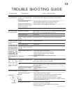
2. Install rigid black pipe, 1/2" type-L copper tubing or, if
local codes permit, a 3/8" flex connector and shutoff valve
to the gas line and the fireplace gas valve. Seal and tighten
securely. An adapter fitting is required between the gas
valve and the copper tubing or flex connector.
DO NOT KINK FLEX CONNECTOR.
3. Check for gas leaks by brushing on a soap and water
solution.
DO NOT USE OPEN FLAME.
It is not necessary to install a hearth extension with this
fireplace system. Objects placed in front of the fireplace
should be kept a minimum of 4 feet away from the front
face.
FIGURE 5
P
I
P
I
L
O
T
3
1
2
N
O
L
O
T
H
I
L
O
F
F
O
FIGURE 6
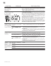
DO NOT CONNECT EITHER THE WALL SWITCH, THER-
MOSTAT OR GAS VALVE TO ELECTRICITY (110
VOLTS).
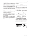
4. For ease of accessibility, an optional remote wall
switch or millivolt thermostat may be installed in a con-
venient location. Route a 2 strand, solid core millivolt wire
from the stove to the wall switch or millivolt thermostat.
The recommended maximum lead length depends on
wire size:
WIRE SIZE MAX. LENGTH
14 gauge 100 feet
16 gauge 60 feet
18 gauge 40 feet
Attach the two leads to terminals 1 and 3 located on the
gas valve.
FINISHING
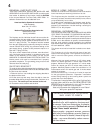
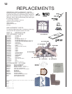
FRONT CAST INSTALLATION
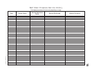
1. Place the cast front face down on a protective surface
such as a carpet or blanket to avoid scratching the fin-
ished surface. Attach the screen to the inside of the front
using four bolts and washers.
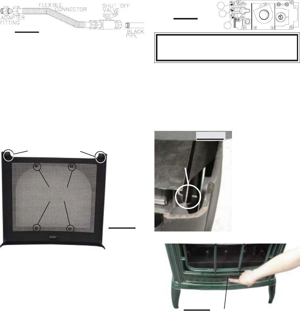
2. Lift the top casting off
the unit.
3. Fit the securing bolts
on the cast front into each
of the respective retainer
brackets (located at ei-
ther side on the top). In-
sert and tighten the se-
curing screw from the
bottom up (located at the
lower center behind the
cast front). This will hold
the cast front in place.
Replace the top casting.
4. To remove the front,
repeat in reverse order.
TOP
FRONT
RETAINER
FIGURE 7b
FIGURE 7a
MESH
SECURING
BOLTS
CAST FRONT
SECURING BOLTS
SECURING
SCREW
FIGURE 7c