


8
W415-0619 / A /08.09.07
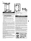
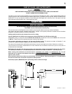
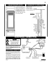
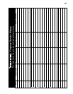
The has been designed to be installed mid-way up an outside wall. When installing this unit close to the fi nished
fl oor, the unit must be raised a minimum of 2” (unobstructed) to allow for full rotation of the control door. It is not necessary
to install a hearth extension.
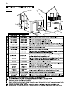
Although the unit fi ts between studs, most jurisdictions will not allow a “hole” in the warm air envelope of a residential structure.
It is recommended to build either an interior or exterior chase with a minimum depth of 7”.
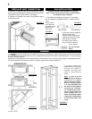
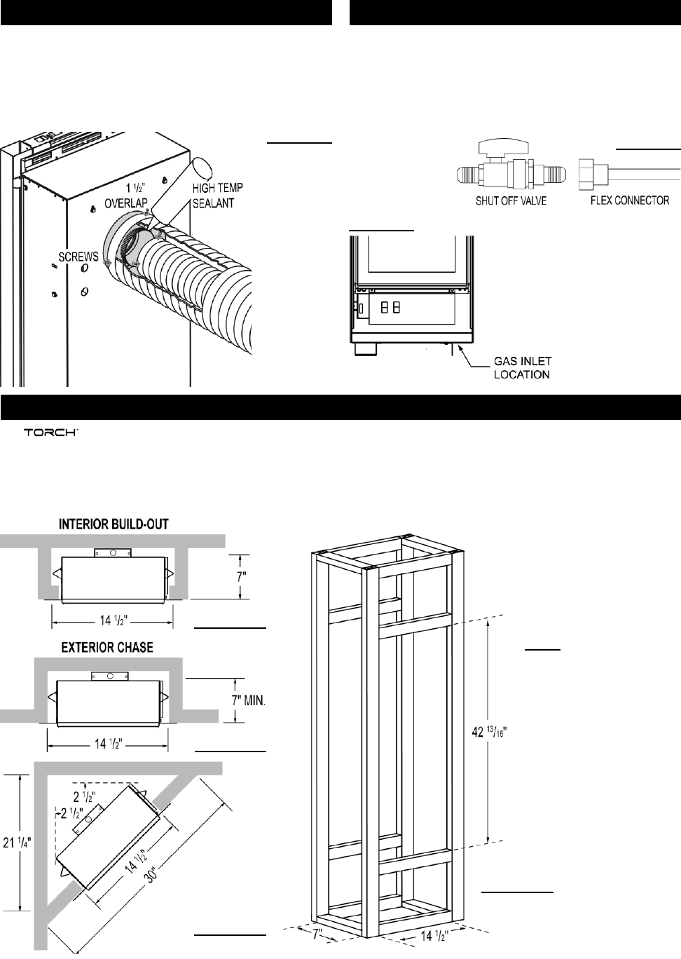
It is best to frame your
fi replace after it is positioned
and the vent system is
installed. Use 2x4’s and
frame to local building
codes.
Note: In order to avoid
the possibility of exposed
insulation or vapour
barrier coming in contact
with the fireplace body,
it is recommended that
the walls of the fi replace
enclosure be “finished”
(ie: drywall/sheetrock),
as you would finish any
other outside wall of a
home. This will ensure that
clearance to combustibles
is maintained within the
cavity.
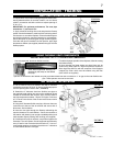
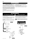
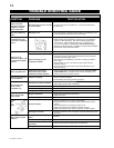
Proceed once the vent installation is complete.
Note : All gas connections must be contained within
the fi replace when complete.
1. The fi replace is designed to accept a
3
/8” gas supply
line. The fi replace is equipped with a
3
/8” manual shut-off
valve.
2. The access
to the gas inlet
is located on the
bottom of the
outer shell.
3. The shut off must always be
within the outer shell.
4. When fl exing any gas line,
support the gas valve so that
the lines are not kinked.
5. Check for gas leaks by
brushing on a soap and
water solution.
Do not use open
fl ame.
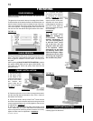
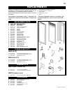
1. Install the 3” diameter vent pipe to the fi replace. Secure
with 3 screws and fl at washers. Seal the joint and screw holes
using Mill Pac sealant (W573-0007 not supplied).
2. Install the 5” diameter vent pipe to the fi replace. Attach
and seal the joints.
FIREPLACE VENT CONNECTION
FIGURE 7
GAS INSTALLATION
FIGURE 9
FIGURE 8
FRAMING
FIGURE 10
FIGURE 11
FIGURE 12
FIGURE 13