


18
W415-0607 / A / 01.18.08
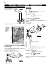
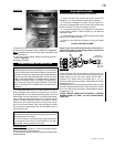
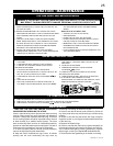
RESTRICTING VERTICAL VENTS
Vertical termination installations exiting either from the rear or the top flue collar of the stove may display a
very active flame. If this appearance is not desirable, the vent exit must be restricted to reduce the velocity of
the exhaust gases, thus slowing down the flame pattern and creating a more traditional gentle appearance.
Remove the baffl e plate from the rear wall of the fi rebox, exposing the fl ue gas outlet opening. Superimpose this outlet hole
with the smaller hole on the kit restrictor plate. Secure with the two screws provided and replace the baffl e plate.
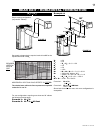
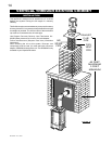
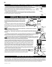
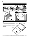
VERTICAL VENTING INSTALLATION
1. Follow the instructions for "Horizontal Air Terminal Installations", items 1 to 3.
2. Continue adding components alternating fl exible and rigid vent pipes. Ensure that all 4"
fl exible vent pipes and elbows have suffi cient vent spacers attached and each component is
securely fastened to the one prior. Attach the 4" telescopic sleeve to the vent run.
Repeat using a 7" telescopic sleeve. Secure and seal as before. To facilitate completion, attach
4" and 7" couplers to the air terminal.
3. Install the air terminal. See item 3 of the Horizontal Air Terminal Installation. Extend the
4" telescopic sleeve; connect to the air terminal assembly. Fasten with self tapping screws
and seal. Repeat using the 7" telescopic sleeve.
FIGURE 26
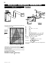
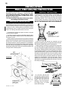
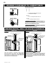
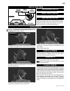
EXTENDED HORIZONTAL AND CORNER AIR TERMINAL INSTALLATION
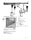
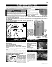
1. Fasten the roof support to the roof using the screws
provided. The roof support is optional. In this case the venting
is to be adequately supported using either an alternate method
suitable to the authority having jurisdiction or the optional roof
support.
2. Stretch the 4" fl exible vent pipe to the required length. Slip
the vent pipe a minimum of 2” over the inner pipe of the air
terminal connector and secure with 3 #8 screws. Seal using a
heavy bead of the high temperature sealant W573-0002 (not
supplied).
NOTE: If using pipe clamps to connect vent components, 3 screws must also be used to
ensure the connection cannot slip off.
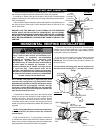
3. Slip the 7" rigid vent pipe a minimum of 2" over the air terminal connector and secure
with 3 #8 screws. Seal using a heavy bead of the high temperature sealant W573-0002 (not
supplied).
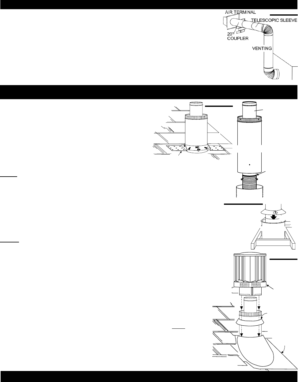
4. Thread the air terminal connector / vent pipe assembly down through the roof. The air terminal
must be located vertically and plumb. Attach the air terminal connector to the
roof support, ensuring
that the top of the air terminal is 16” above the highest point that penetrates the roof.
If the attic space is tight, we recommend threading the Wolf Steel vent pipe collar or equivalent
loosely onto the air terminal connector / vent pipe assembly as it is passed through the attic.
The air terminal connector must be located vertically and plumb.
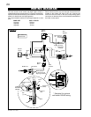
5. Remove nails from the shingles, above and to the sides of the chimney. Place the
fl ashing over the air terminal connector leaving a min. 3/4” of the air terminal connector
showing above the top of the fl ashing. Slide the fl ashing underneath the sides and
upper edge of the shingles. Ensure that the air terminal connector is properly centred
within the fl ashing, giving a 3/4” margin all around. Fasten to the roof. Do not nail
through the lower portion of the fl ashing. Make weather-tight by sealing with caulking.
Where possible, cover the sides and top edges of the fl ashing with roofi ng material.
6. Aligning the seams of the terminal and air terminal connector, place the terminal
over the air terminal connector making sure the inner pipe goes into the hole in the
terminal. Secure with the three screws provided.
7. Apply a heavy bead of weatherproof caulking 2" above the fl ashing. Note: Maintain
a minimum 2” space between the air inlet base and the storm collar. Install the storm
collar around the air terminal and slide down to the caulking. Tighten to ensure that a
weather-tight seal between the air terminal and the collar is achieved.
ROOF SUPPORT
AIR
TERMINAL
CONNECTOR
4” FLEX
VENT PIPE
7” RIGID
VENT PIPE
INNER
PIPE
HIGH
TEMPERATURE
SEALANT
STORM COLLAR
FLASHING
CAULKING
WEATHER
SEALANT
2”
AIR INLET
BASE
FIGURE 27
FIGURE 28a&b
FIGURE 29
SHIELD
VENT
PIPE
COLLAR
VENT PIPE