


21
W415-0547 / C / 07.25.06
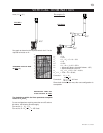
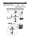
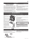
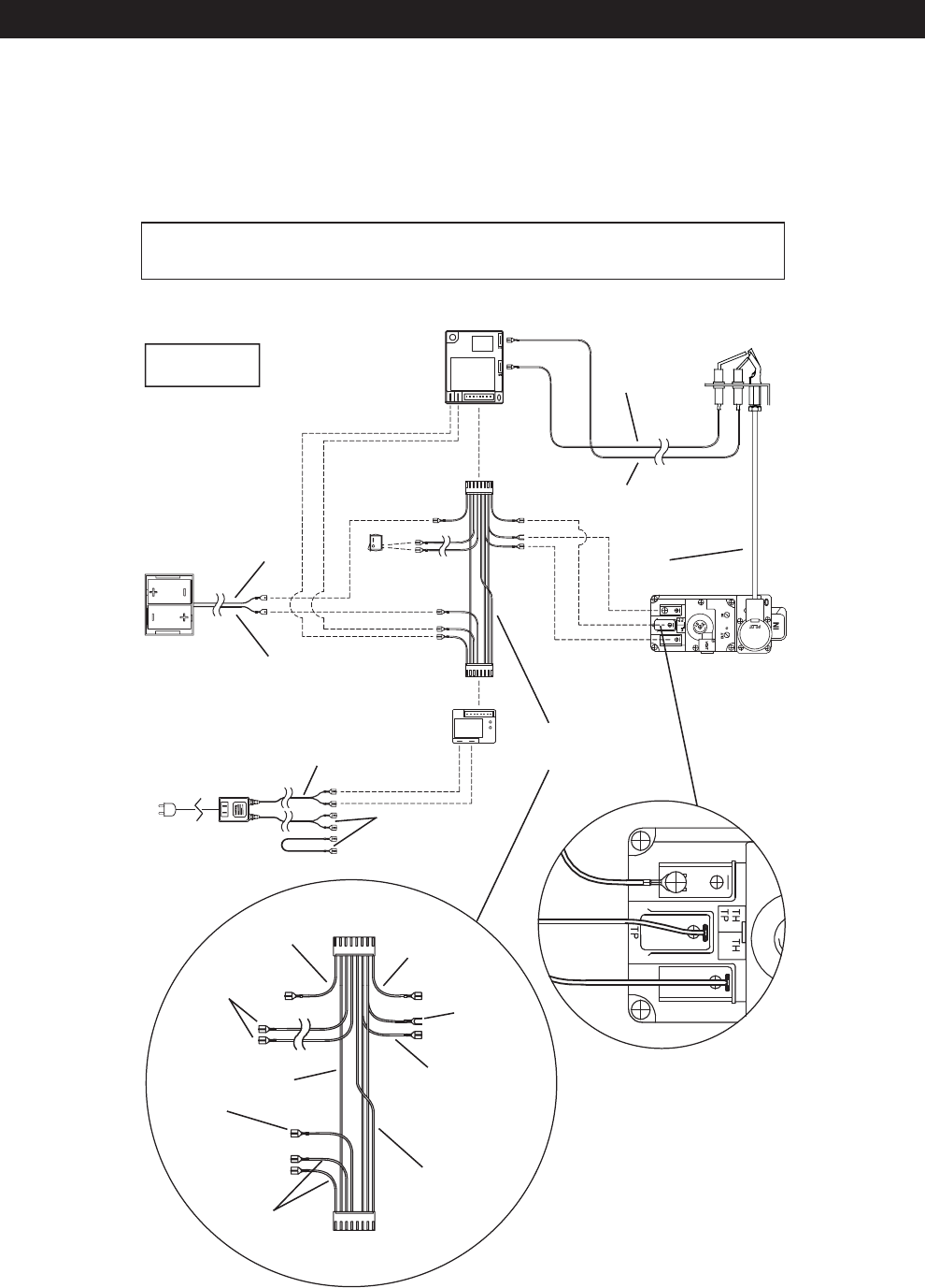
OPTIONAL SWITCH / WIRING DIAGRAM
The on/off switch is located on the back of the
GDS25 at the top right corner. For ease of acces-
sibility, an optional remote wall switch or millivolt
thermostat may be installed in a convenient location.
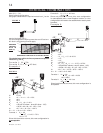
The recommended maximum lead length depends on
wire size:
WIRE SIZE MAX. LENGTH
14 gauge 100 feet
16 gauge 60 feet
18 gauge 40 feet
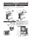
Route 2-strand (solid core) wire through the electri-
cal hole located at the bottom left side of the unit.
Connect the wires from the wall switch / thermostat
to the two brown wires extending from the fi replace
mounted ignition control box.
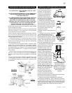
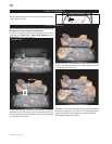
Purge all gas lines with the glass door of the fi replace open.
Assure that a continuous gas fl ow is at the burner before closing the door.
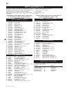
BURNER
SWITCH /WALL
THERMOSTAT
BATTERY
HOLDER
GAS VALVE
PILOT
ASSEMBLY
IGNITION
MODULE
PILOT
GAS LINE
Orange
(I)
[through
independent
conduit]
Yellow
(S)
[through
Gas line
conduit]
AC ADAPTOR
BATTERY
RELAY
Red (3 Volt)
Red
Black
WIRE
HARNESS
NOTE: WIRE TAGS
ARE BRACKETED
Brown
(SWI)
Black
(-)
Red
(+)
Green x2
(TH)
Orange x2
(THTP)
Black
Yellow
Blue
Black
(TP)
MODULE
PLUG
RELAY
PLUG
Black
Green
Orange
Black (12 Volt)
To Accent Light &
Accent Light Switch