16
W415-0434 / C / 03.24.05
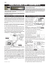
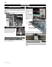
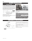
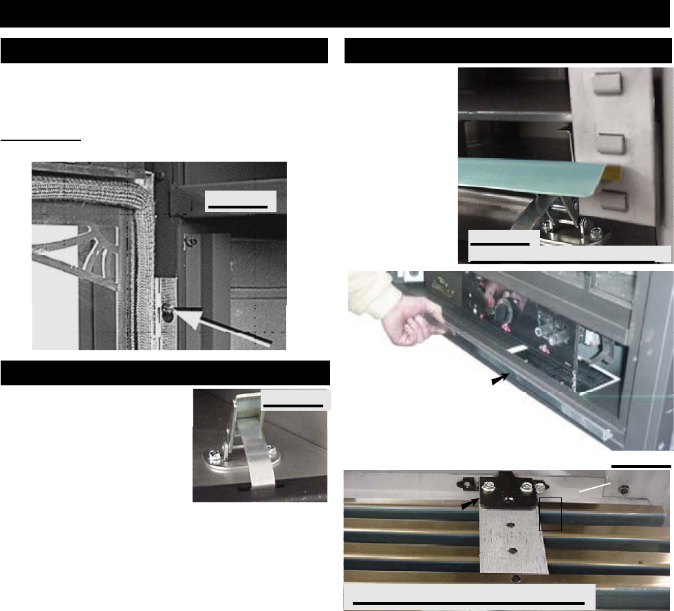
Open the valve control door.
Hook the top and bottom door
latches, located at the right
side of the door into the corre-
sponding slots in the door.
The door latch holes are elongated for door levelling. To
level the door, it may need to be lifte
d up at the right
side before latching to ensure the door is level.
Prior to opening the door, lift up and remove the upper lou-
vres or ornamental insets.
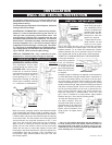
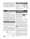
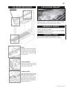
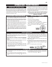
HINGE SCREEN
Remove the hinge screen, if factory installed.
Screw the lower louvre assembly to the lip of the fireplace
base as shown. Position the hinge screen into place and
with the control door open, secure to the firebox using three
screws.
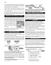
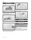
Remove the pro-
tective plastic wrap
from the louvres
and install as illus-
trated.
Clip each upper
louvre into a slot on
the louvre bracket.
Ensure that the
louvres are cen-
tered within the
opening.
FIGURE 42: LOWER LOUVRE ASSEMBLY
LOUVRE
BRACKET
FIGURE 40
UPPER LOUVRE INSTALLATION
FIGURE 41
FIGURE 39
DOOR CLOSING AND OPENING
GDLV LOUVRE INSTALLATION
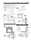
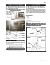
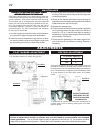
Loosely thread a screw provided with the door kit into the
top hole on the left side of the firebox. Hang the door by the
hinge onto the screw. Insert the remaining 4 screws and
tighten.
IMPORTANT:
Ensure screws are driven in straight or the
hole thread may be damaged.
FINISHING
DOOR INSTALLATION
FIGURE 38
HINGE
SCREEN


