


5
W415-0100 / D / 01.13.04
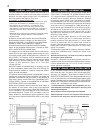
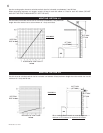
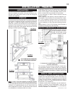
FIGURE 3
• Under extreme vent configurations, allow several min-
utes (5-15) for the flame to stabilize after ignition.
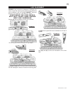
• Eight (8") inches is the minimum bend radius allowed for
the 7" diameter flexible air liner.
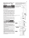
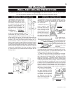
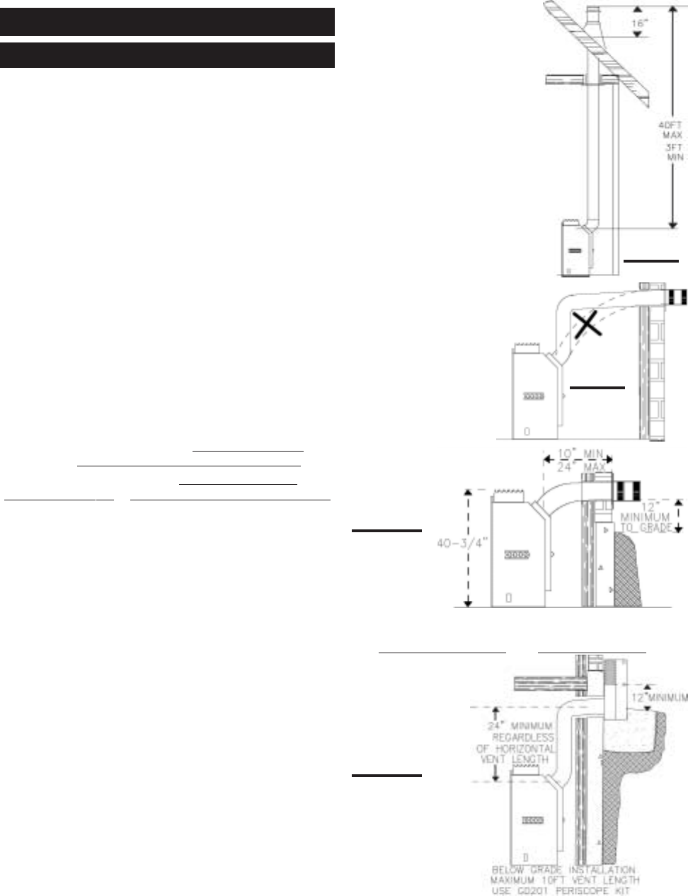
When terminating vertically, the
vertical rise is a minimum 36
inches and a maximum 40 feet
above the fireplace.
Do not radius vertical vent
rises.
When venting, the immediate horizontal run must be kept
to a
minimum of 10 inches or a maximum of 3 feet.
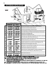
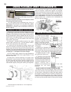
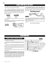
Minimum clearance to combustible construc-
tion from fireplace and vent surfaces:
sides, back, bottom, and top 0 inches
vent pipe 1 inch
recessed depth 22 inches
Use only Napoleon or Simpson Dura-Vent Model DV-GS
venting components. Minimum and maximum vent lengths,
for both horizontal and vertical installations, and air termi-
nal locations for either system are set out in this manual
and must be adhered to.
When using Napoleon venting components, use only the
following vent kits: WALL TERMINAL KIT GD-222R, or 1/12
TO 7/12 PITCH ROOF TERMINAL KIT GD-110, 8/12 TO 12/
12 ROOF TERMINAL KIT GD-111, FLAT ROOF TERMINAL
KIT GD-112 or PERISCOPE KIT GD-201 (for wall penetra-
tion below grade) in conjunction with the various termina-
tions, use either the 5 foot vent kit GD-220 or the 10 foot
vent kit GD-330 For Simpson Dura-Vent, follow the installa-
tion procedure provided with the venting components.
These vent kits allow for either horizontal or vertical venting
of the fireplace. The maximum number of 4" flexible con-
nections is four (excluding the fireplace and the air termi-
nal connections).
For optimum flame appearance and fireplace performance,
keep the vent length and number of elbows to a minimum.
The air terminal must remain unobstructed at all times.
Examine the air terminal at least once a year to verify that it
is unobstructed and undamaged.
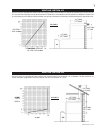
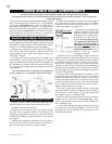
• All horizontal runs must have a
1 inch rise per foot in all
cases using Napoleon flexible venting components.
• Horizontal runs can have a 0 inch rise per foot using
Simpson Dura-Vent or Napoleon rigid venting components.
For optimum performance, it is recommended that all hori-
zontal runs have a minimum ¼ inch rise per foot using
rigid venting.
• Provide a means for visually checking the vent connec-
tion to the fireplace after the fireplace is installed.
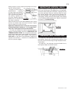
• Do not allow the inside liner to bunch up on horizontal or
vertical runs and elbows. Keep it pulled tight. A 1¼" air
gap between the inner and outer liner all around is re-
quired for safe operation.
• Use a firestop when penetrating interior walls, floor or
ceiling.
• For safe and proper operation of the fireplace follow the
venting instruction exactly.
• Deviation from the minimum vertical vent length can cre-
ate difficulty in burner start-up and/or carboning.
• Vent lengths that pass through unheated spaces (attics,
garages, crawl space) should be insulated with the insu-
lation wrapped in a protective sleeve to minimize conden-
sation.
• Purge all gas lines with the glass door of the fireplace
open. Assure that a continuous gas flow is at the burner
before closing the door.
FIGURE 2
FIGURES 4a
FIGURES 4b
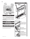
VENTING
VENTING LENGTHS