


12
W415-0100 / D / 01.13.04
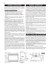
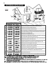
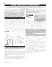
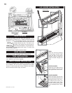
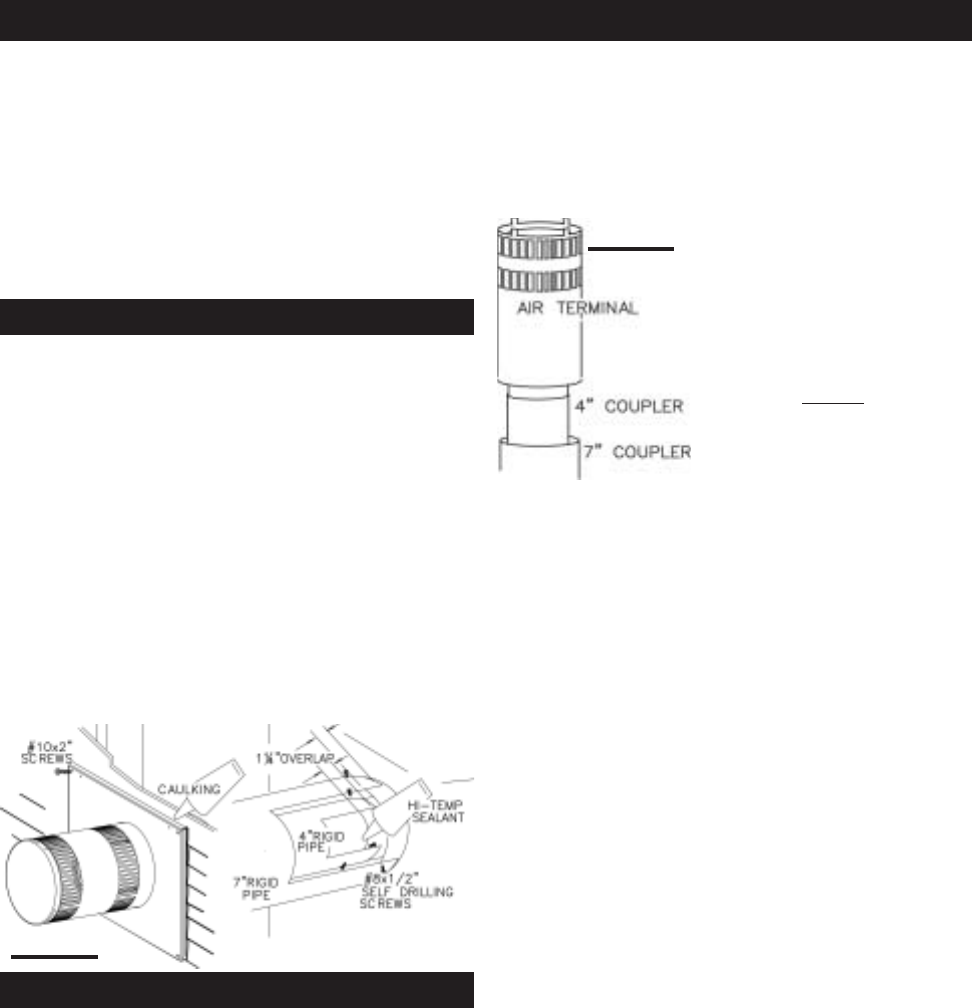
FIGURE 22
The vent system must be supported approximately every 3
feet for both vertical and horizontal runs. Use Wolf Steel
vent spacers W615-0033 every 3 feet and either side of
each elbow to maintain the minimum 1¼" clearance be-
tween the outer and inner vent pipes. Use Wolf Steel sup-
port ring assembly W010-0370 or equivalent noncombus-
tible strapping to maintain the minimum 1" clearance to
combustibles for both vertical and horizontal runs.
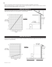
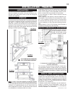
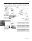
1. Move the fireplace into position. Measure the vent length
required between terminal and fireplace taking into account
the additional length needed for the finished wall surface
and any 1¼" overlaps between venting components.
2. Apply high temperature sealant to the outer edge of
the 4" inner collar of the fireplace. Attach the first vent
component and secure using 3 self tapping screws. Re-
peat using 7" piping.
3. Holding the air terminal (lettering in an upright, read-
able position), insert into both vent pipes with a twisting
motion to ensure that both the terminal sleeves engage into
the vent pipes and sealant. Secure the terminal to the exte-
rior wall and make weather tight by sealing with caulking
(not supplied).
The air terminal may be recessed into the exterior
wall or siding by 1½", the depth of the return flange.
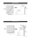
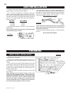
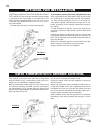
1. Attach 4" and 7" elbows to the stove. Apply high tem-
perature sealant and secure the joints with 3 screws.
2. Move the fireplace into position.
3. Fasten the roof support to the roof using the screws
provided. The roof support is optional. The venting is to be
adequately supported using either an alternate method
suitable to the authority having jurisdiction or the optional
roof support.
4. Apply high temperature sealant to the outer edge of
the inner sleeve of the air terminal. Slip a 4" diameter cou-
pler over the sleeve and secure using 3 screws.
5. Apply high temperature sealant to the outer edge of
the outside sleeve of the air terminal. Slip a 7" diameter
coupler over the sleeve and secure as before. Trim the 7"
coupler even with the 4" coupler end.
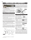
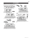
6. Thread the air terminal pipe
assembly down through the roof
support and attach, ensuring that
a minimum 16" of air terminal will
penetrate the roof when fas-
tened. If the attic space is tight,
we recommend threading the
Wolf Steel vent pipe collar or
equivalent
loosely onto the air
terminal assembly as it is
passed through the attic. The air
terminal must be located
vertically and plumb.
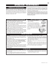
7. Remove nails from the shingles, above and to the
sides of the chimney. Place the flashing over the air termi-
nal and slide it underneath the sides and upper edge of
the shingles. Ensure that the air terminal is properly cen-
tred within the flashing, giving a 3/4" margin all around.
Fasten to the roof. Do NOT nail through the lower portion of
the flashing. Make weather-tight by sealing with caulking.
Where possible, cover the sides and top edges of the flash-
ing with roofing material.
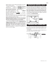
8. Apply a heavy bead of waterproof caulking 2 inches
above the flashing. Slide the storm collar around the air
terminal and down to the caulking. Tighten to ensure that a
weather-tight seal between the air terminal and the collar
is achieved. Attach the other storm collar centred between
the air intake and air exhaust slots onto the air terminal.
Tighten securely. Attach the rain cap.
9. Continue adding rigid venting sections, sealing and
securing as above. Attach a 4" collapsed telescopic pipe to
the last section of rigid piping. Secure with screws and
seal. Repeat using a 7" telescopic pipe.
10. Run a bead of high temperature sealant around the
outside of the 4" elbow. Pull the adjustable pipe a mini-
mum 2" onto the elbow. Secure with 3 screws. Repeat with
the 7" telescopic pipe.
11. In the attic, slide the vent pipe collar down to cover up
the open end of the shield and tighten. This will prevent
any materials, such as insulation, from filling up the 1" air
space around the pipe.
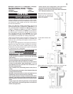
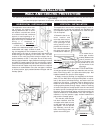
FIGURE 23
USING RIGID VENT COMPONENTS
For safe and proper operation of the fireplace, follow the venting instructions exactly.
For optimum performance, it is recommended that all horizontal runs have a minimum ¼ inch rise per foot
using rigid venting.
HORIZONTAL AIR TERMINAL INSTALLATION
VERTICAL VENTING INSTALLATION